
How to Design an ISBM Mold for a New Bottle: Practical Technical Guide
The useful answer to How to Design an ISBM Mold for a New Bottle comes from the interaction between bottle drawing, blow cavity, and trial loop. The sections below turn those factors into checks that can be repeated on a production machine.
Bottle drawingBlow cavityTrial loop
What this article must prove
Design the complete isbm tooling concept for a new bottle by linking bottle drawing, preform, neck/lip tooling, conditioning, blow cavity, base insert, cooling, venting, stretch rod and machine interfaces. A defensible baseline begins with Define volume, mass target, neck finish, body envelope, parting line, base, decoration panels and tolerances that matter to function. The first verification method is Use one controlled drawing revision for bottle, mold and machine teams. From there, the article follows only checks that can materially change the answer promised by the title. Where an exact operating value depends on the resin grade, bottle drawing, mold, or delivered machine, the approved project specification controls the final setting.
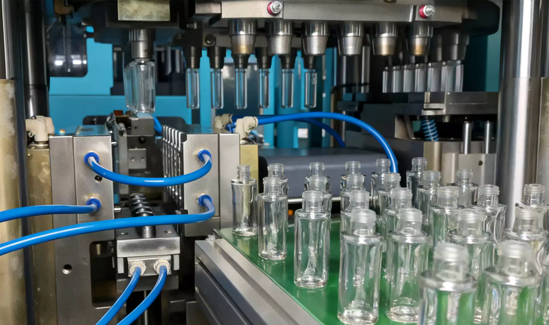
✔️ Bottle drawing
Define volume, mass target, neck finish, body envelope, parting line, base, decoration panels and tolerances that matter to function. Use one controlled drawing revision for bottle, mold and machine teams.
✔️ Preform concept
Allocate material to shoulder, body and base based on stretch demand rather than making a uniform tube by default. Calculate geometric stretch ratios and review likely local surface-area expansion.
✔️ Core and cavity
Design the injection preform tooling for balanced fill, cooling and release. Check core stiffness, gate alignment, hot-runner balance and cooling access.
The ASB-compatible tooling configuration is also relevant when checking how mold interfaces and machine motion must remain compatible during replacement, troubleshooting, or capacity changes.
Freeze the Bottle and Closure Requirements
Bottle drawing
Bottle drawing. Define volume, mass target, neck finish, body envelope, parting line, base, decoration panels and tolerances that matter to function. Use one controlled drawing revision for bottle, mold and machine teams. Resolve bottle drawing before final tooling release when possible because a geometry error is much harder to compensate with process settings. Keep bottle drawing at its validated baseline while this item is tested so the bottle response can be attributed to one cause. Late uncontrolled design changes can invalidate preform and cavity geometry.
Design the Preform around Material Movement
Preform concept
Preform concept. Allocate material to shoulder, body and base based on stretch demand rather than making a uniform tube by default. Calculate geometric stretch ratios and review likely local surface-area expansion. Resolve preform concept before final tooling release when possible because a geometry error is much harder to compensate with process settings. Use the smallest controlled change that can prove the effect of preform concept, then restore the baseline before a different adjustment such as preform concept is tried. A poor preform can force extreme thermal tuning and a narrow production window.
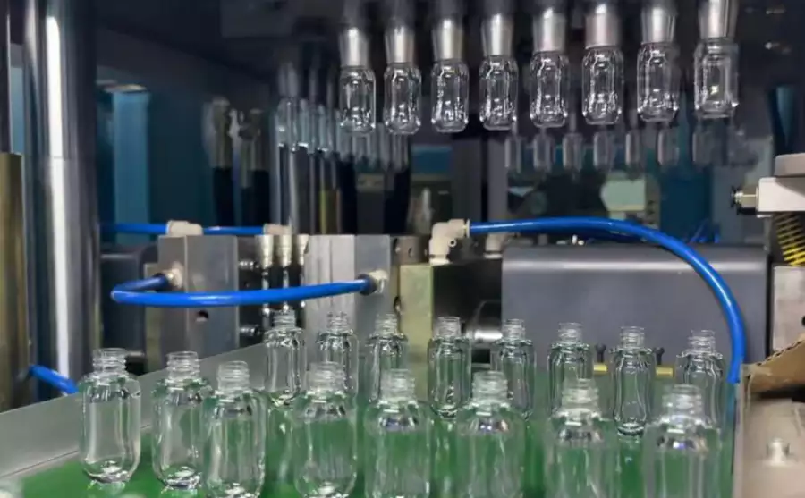
Design the Injection and Lip Tooling
Core and cavity
Core and cavity. Design the injection preform tooling for balanced fill, cooling and release. Check core stiffness, gate alignment, hot-runner balance and cooling access. Resolve core and cavity before final tooling release when possible because a geometry error is much harder to compensate with process settings. This factor belongs in the setup sheet because it directly changes the conditions under which core and cavity is evaluated. Core deflection or unbalanced flow creates preforms that no blow recipe can make identical.
Lip cavity
Lip cavity. The neck finish must be formed accurately and retained through transfers. Provide cooling, alignment and wear surfaces suitable for repeated indexing. Resolve lip cavity before final tooling release when possible because a geometry error is much harder to compensate with process settings. If the result differs by cavity, compare the local hardware related to lip cavity before moving on to lip cavity. Lip wear or poor cooling becomes closure variation.
Working terms for this specific task
- Bottle drawing
- Define volume, mass target, neck finish, body envelope, parting line, base, decoration panels and tolerances that matter to function.
- Preform concept
- Allocate material to shoulder, body and base based on stretch demand rather than making a uniform tube by default.
- Core and cavity
- Design the injection preform tooling for balanced fill, cooling and release.
- Lip cavity
- The neck finish must be formed accurately and retained through transfers.
Design Conditioning for the Hardest Wall-Distribution Problem
Conditioning tooling
Conditioning tooling. Decide where additional heat removal or addition is needed between injection and blowing. Plan zones around thick regions, neck transition and non-round bottle directions. Resolve conditioning tooling before final tooling release when possible because a geometry error is much harder to compensate with process settings. This item is considered resolved only when the finding remains repeatable after thermal stabilization and the next check, conditioning tooling, does not contradict it. Conditioning designed after the mold is built may be difficult to add effectively.
| مورد | Engineering question | Practical verification |
|---|---|---|
| Bottle drawing | Define volume, mass target, neck finish, body envelope, parting line, base, decoration panels and tolerances that matter to function. | Use one controlled drawing revision for bottle, mold and machine teams. |
| Preform concept | Allocate material to shoulder, body and base based on stretch demand rather than making a uniform tube by default. | Calculate geometric stretch ratios and review likely local surface-area expansion. |
| Core and cavity | Design the injection preform tooling for balanced fill, cooling and release. | Check core stiffness, gate alignment, hot-runner balance and cooling access. |
| Lip cavity | The neck finish must be formed accurately and retained through transfers. | Provide cooling, alignment and wear surfaces suitable for repeated indexing. |
| Conditioning tooling | Decide where additional heat removal or addition is needed between injection and blowing. | Plan zones around thick regions, neck transition and non-round bottle directions. |
| Blow cavity | Choose parting line, draft, surface texture, engraving and split construction around bottle appearance and release. | Avoid placing critical decoration or sealing features where mold split or vent marks are unacceptable. |
| Release condition | Run the intended resin, measure preform and bottle by cavity, and correct tooling before final hardening or production release where feasible. Use wall maps, visual defects and dimensional data to decide whether to change process or steel. | |
Design the Blow Cavity and Parting Line
Blow cavity
Blow cavity. Choose parting line, draft, surface texture, engraving and split construction around bottle appearance and release. Avoid placing critical decoration or sealing features where mold split or vent marks are unacceptable. Resolve blow cavity before final tooling release when possible because a geometry error is much harder to compensate with process settings. For repeatability, define who measures blow cavity, where it is measured, and what bottle evidence is required before checking blow cavity. A poor parting-line location can create permanent cosmetic problems.
For tooling-related decisions, the ASB-12 replacement mold engineering highlights why dimensional interfaces, cooling connections, cavity geometry, and transfer alignment must be treated as part of the machine setup.
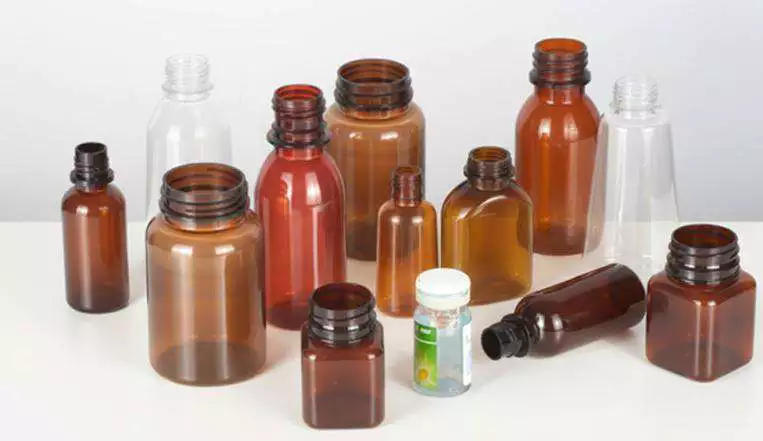
Design Base Insert, Venting and Cooling
Base insert
Base insert. Design the gate area, push-up, feet and cooling as a serviceable insert where practical. Provide venting and water paths close to the hot base mass. Resolve base insert before final tooling release when possible because a geometry error is much harder to compensate with process settings. Record the bottle response beside the setting or measurement for base insert; that record becomes the starting condition when base insert is reviewed. Inadequate base cooling can dictate the whole cycle time.
Venting
Venting. Provide paths for cavity air to escape at last-fill regions and fine details. Design vents for cleaning and maintenance access. Resolve venting before final tooling release when possible because a geometry error is much harder to compensate with process settings. If the symptom or performance target does not move as predicted, return venting to the baseline and investigate venting rather than stacking corrections. Blocked or undersized vents lead to poor definition and can tempt operators to raise pressure unnecessarily.
Check Machine Interfaces and Movements
Machine interface
Machine interface. Verify mold dimensions, bolt pattern, locating features, strokes, transfer pitch, stretch-rod travel, take-out and hose routing. Perform a digital or physical interference review through all machine motions. Resolve machine interface before final tooling release when possible because a geometry error is much harder to compensate with process settings. If a change improves one region but worsens another, compare the material or energy movement between machine interface and machine interface instead of accepting the first visual improvement. A mold can be correct as a standalone tool and still collide with the machine.
Prototype, Trial and Correct Before Production Release
Trial loop
Trial loop. Run the intended resin, measure preform and bottle by cavity, and correct tooling before final hardening or production release where feasible. Use wall maps, visual defects and dimensional data to decide whether to change process or steel. Resolve trial loop before final tooling release when possible because a geometry error is much harder to compensate with process settings. Where the outcome depends on material grade or tooling geometry, confirm the approved project limit and then use trial loop as the next cross-check. Repeated process compensation for a tooling geometry error creates long-term scrap.
Machine interface: release evidence
Verify mold dimensions, bolt pattern, locating features, strokes, transfer pitch, stretch-rod travel, take-out and hose routing. Perform a digital or physical interference review through all machine motions. The condition is accepted only when the relevant bottle measurement or functional test remains stable after the process reaches normal operating temperature.
Trial loop: failure boundary
Repeated process compensation for a tooling geometry error creates long-term scrap. Use that failure mode as the boundary for the trial and return to the previous stable condition when the bottle response moves in the wrong direction.
A demanding shape case such as the wide-mouth container ISBM application is useful for checking whether the same process logic remains stable when projected area, heat balance, and material distribution become harder to control.
Questions that arise specifically in How to Design an ISBM Mold for a New Bottle
Should preform design start after the bottle mold is finished?
No. Bottle, preform and tooling should be developed together because material distribution and machine interfaces are linked.
What part of the mold often controls cycle time?
Any region with high heat load can become limiting; thick preform sections and bottle base cooling are common areas to examine.
Why make the base an insert?
It can simplify cooling design, venting, service and future base changes, depending on mold architecture.
How do I choose the parting line?
Balance manufacturability, release, venting, bottle appearance and whether decoration or functional surfaces can tolerate a seam.
What should be proven in the first mold trial?
Preform balance, wall distribution, dimensions, appearance, release, cooling stability and the complete machine movement envelope.
Practical conclusion
A robust answer to How to Design an ISBM Mold for a New Bottle should survive a restart and a full thermal stabilization period. The setup record should therefore connect bottle drawing with blow cavity and the bottle result from trial loop. A poor parting-line location can create permanent cosmetic problems.