How Cooling Time Affects the ISBM Cycle: Practical Technical Guide
For How Cooling Time Affects the ISBM Cycle, the objective is not to find one universal setting. It is to prove which combination of injection cooling, conditioning residence, and bottleneck test produces the required bottle under stable factory conditions.
Injection coolingNeck-area coolingValidation
Ce que cet article doit prouver
Understand how cooling time and cooling balance affect preform release, thermal conditioning, bottle demolding, dimensional stability, cycle time and delayed deformation. A defensible baseline begins with The preform must be rigid enough to transfer while retaining the thermal state needed for later stretching. The first verification method is Reduce injection cooling only in small steps while watching preform release, neck dimensions and the bottle response downstream. From there, the article follows only checks that can materially change the answer promised by the title. Where an exact operating value depends on the resin grade, bottle drawing, mold, or delivered machine, the approved project specification controls the final setting.
✔️ Injection cooling
The preform must be rigid enough to transfer while retaining the thermal state needed for later stretching. Reduce injection cooling only in small steps while watching preform release, neck dimensions and the bottle response downstream.
✔️ Core and cavity balance
Cooling on the inside and outside of the preform affects through-wall temperature gradients. Monitor circuit flow and return temperature and compare cavities.
✔️ Conditioning residence
Time between injection and blow allows heat to redistribute through the preform wall. After changing cycle time, recheck the bottle thickness map even if heater settings are unchanged.
Le Conception du moule de remplacement ISBM renforce la nécessité pratique de contrôler la géométrie de montage, le comportement thermique, la position de transfert et l'alignement de la cavité plutôt que de traiter le moule comme un composant isolé.
Cooling Appears in More Than One ISBM Stage
Injection cooling
Injection cooling. The preform must be rigid enough to transfer while retaining the thermal state needed for later stretching. Reduce injection cooling only in small steps while watching preform release, neck dimensions and the bottle response downstream. Observe when the effect of injection cooling first appears in the cycle; that timing helps separate cause from symptom. Where the outcome depends on material grade or tooling geometry, confirm the approved project limit and then use injection cooling as the next cross-check. A preform that transfers cleanly may still be too hot internally and stretch differently after several minutes of thermal drift.
Injection Cooling Controls Preform Release and Heat Memory
Core and cavity balance
Core and cavity balance. Cooling on the inside and outside of the preform affects through-wall temperature gradients. Monitor circuit flow and return temperature and compare cavities. Observe when the effect of core and cavity balance first appears in the cycle; that timing helps separate cause from symptom. When the project is near a machine or material limit, require a molding trial that isolates core and cavity balance and then challenges core and cavity balance under the same bottle specification. Uneven circuits can create identical-looking preforms that blow differently.
Conditioning residence
Conditioning residence. Time between injection and blow allows heat to redistribute through the preform wall. After changing cycle time, recheck the bottle thickness map even if heater settings are unchanged. Observe when the effect of conditioning residence first appears in the cycle; that timing helps separate cause from symptom. The safest interpretation comes from comparing at least several stable cycles and then verifying conditioning residence without changing the rest of the recipe. Faster indexing changes the thermal profile and may shift material distribution.
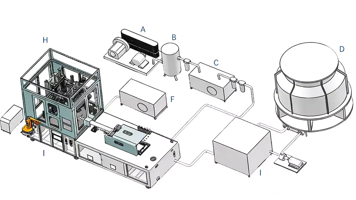
Conditioning Time Changes the Blow Window
Blow-mold cooling
Blow-mold cooling. The bottle must release with sufficient shape stability, especially at base, neck transition and wide panels. Observe bottle temperature and dimensions immediately after ejection and after a defined stabilization period. Observe when the effect of blow-mold cooling first appears in the cycle; that timing helps separate cause from symptom. A useful production trial keeps the resin lot and cavity identification fixed while blow-mold cooling is changed, followed by a separate check of blow-mold cooling. A bottle can pass an immediate visual check and then ovalize or rock on its base later.
Conditions de travail pour cette tâche spécifique
- Injection cooling
- The preform must be rigid enough to transfer while retaining the thermal state needed for later stretching.
- Core and cavity balance
- Cooling on the inside and outside of the preform affects through-wall temperature gradients.
- Conditioning residence
- Time between injection and blow allows heat to redistribute through the preform wall.
- Blow-mold cooling
- The bottle must release with sufficient shape stability, especially at base, neck transition and wide panels.
Blow-Mold Cooling Controls Shape Freeze
Base insert cooling
Base insert cooling. Thick base regions and push-up geometry can retain heat. Check for local deformation, sticking or excessive base temperature and inspect water flow through the base insert. Observe when the effect of base insert cooling first appears in the cycle; that timing helps separate cause from symptom. The practical value of this check is that it turns base insert cooling from a vague setting into evidence that can be compared with base insert cooling. Reducing base cooling too aggressively often creates downstream standing or leak-test issues.
Neck-area cooling
Neck-area cooling. The injection-molded finish must stay within dimensional limits through the integrated cycle. Measure closure-critical features after stable production and after any cycle reduction. Observe when the effect of neck-area cooling first appears in the cycle; that timing helps separate cause from symptom. Use this result to narrow the process window, not to create a new universal setpoint; the next constraint to confirm is neck-area cooling. A small neck distortion may not be visible but can appear as capping or leak failure.
Pour ce sujet, le portefeuille de machines ISBM en une étape fournit un contexte utile sur les équipements pour relier les exigences du processus à une plateforme intégrée de résine à bouteille.
| Article | Question d'ingénierie | vérification pratique |
|---|---|---|
| Injection cooling | The preform must be rigid enough to transfer while retaining the thermal state needed for later stretching. | Reduce injection cooling only in small steps while watching preform release, neck dimensions and the bottle response downstream. |
| Core and cavity balance | Cooling on the inside and outside of the preform affects through-wall temperature gradients. | Monitor circuit flow and return temperature and compare cavities. |
| Conditioning residence | Time between injection and blow allows heat to redistribute through the preform wall. | After changing cycle time, recheck the bottle thickness map even if heater settings are unchanged. |
| Blow-mold cooling | The bottle must release with sufficient shape stability, especially at base, neck transition and wide panels. | Observe bottle temperature and dimensions immediately after ejection and after a defined stabilization period. |
| Base insert cooling | Thick base regions and push-up geometry can retain heat. | Check for local deformation, sticking or excessive base temperature and inspect water flow through the base insert. |
| Neck-area cooling | The injection-molded finish must stay within dimensional limits through the integrated cycle. | Measure closure-critical features after stable production and after any cycle reduction. |
| Conditions de libération | After each cooling reduction, evaluate dimensions, wall distribution, visual quality, base flatness and downstream handling over a stable run. Keep the change only if bottle quality and process margin remain acceptable. | |
What Happens When Cooling Is Cut Too Far
Cooling-water quality
Cooling-water quality. Scale, fouling and blocked strainers reduce heat transfer even when water temperature at the chiller is correct. Trend flow or pressure drop and inspect circuits during preventive maintenance. Observe when the effect of cooling-water quality first appears in the cycle; that timing helps separate cause from symptom. The expected response should be visible in a bottle measurement, defect map, or machine trend before the team proceeds to cooling-water quality. Operators may compensate for fouled cooling by lengthening cycle instead of correcting the utility problem.
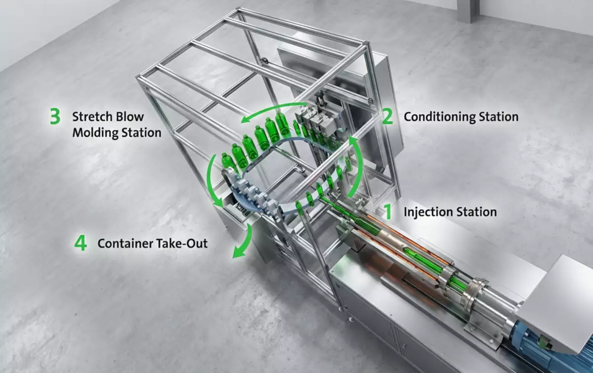
How to Find the Real Cooling Bottleneck
Chiller capacity
Chiller capacity. Cooling demand rises with resin throughput and ambient conditions. Compare supply/return temperatures during full production and when other equipment shares the chiller. Observe when the effect of chiller capacity first appears in the cycle; that timing helps separate cause from symptom. Once this check is stable, the next useful question is whether chiller capacity changes the same bottle region or affects a different part of the process. A chiller sized near its limit can cause seasonal cycle-time drift.
Bottleneck test
Bottleneck test. Record actual station times and identify where additional cooling truly controls the index. Shorten only the limiting cooling stage and verify quality before touching other stations. Observe when the effect of bottleneck test first appears in the cycle; that timing helps separate cause from symptom. This checkpoint should be evaluated before bottleneck test is altered, because otherwise two process mechanisms change at the same time. Removing time from a non-limiting stage does not increase output.
Reduce Cooling Time without Creating Delayed Defects
Validation
Validation. After each cooling reduction, evaluate dimensions, wall distribution, visual quality, base flatness and downstream handling over a stable run. Keep the change only if bottle quality and process margin remain acceptable. Observe when the effect of validation first appears in the cycle; that timing helps separate cause from symptom. For this topic, the engineering log should connect validation with the observed bottle condition and then test whether validation supports the same diagnosis. The shortest cycle is not the best cycle if scrap or delayed deformation increases.
Bottleneck test: release evidence
Record actual station times and identify where additional cooling truly controls the index. Shorten only the limiting cooling stage and verify quality before touching other stations. The condition is accepted only when the relevant bottle measurement or functional test remains stable after the process reaches normal operating temperature.
Validation : limite de défaillance
The shortest cycle is not the best cycle if scrap or delayed deformation increases. Use that failure mode as the boundary for the trial and return to the previous stable condition when the bottle response moves in the wrong direction.
Le Aperçu de la plateforme ISBM multi-matériaux permet également de définir comment l'architecture des machines, les matériaux, les utilités et les applications de bouteilles s'articulent au niveau de la ligne de production.
Questions that arise specifically in How Cooling Time Affects the ISBM Cycle
Why can a bottle deform after it leaves the mold?
Residual heat and internal stress can continue to relax after ejection, especially when base or panel cooling is insufficient.
Does colder cooling water always shorten cycle?
Not necessarily. Heat transfer also depends on flow, channel design, fouling and the resin process window, and excessive cooling can create other molding problems.
Why re-tune temperature after reducing cycle time?
The preform spends less time redistributing heat between stages, so the thermal profile at blowing changes.
How do I know whether the chiller is limiting production?
Check supply and return temperatures, flow, load stability and whether conditions drift when production or ambient load rises.
Can I reduce cooling by increasing blow pressure?
Pressure and cooling solve different problems. Higher air pressure does not replace the heat removal needed for dimensional stability.
Conclusion pratique
The final decision on How Cooling Time Affects the ISBM Cycle is made by the bottle, not by a single displayed parameter. Use injection cooling to establish the input, neck-area cooling to test the mechanism, and validation to prove the output under stable conditions. The shortest cycle is not the best cycle if scrap or delayed deformation increases.