
How to Set Up an ISBM Machine Step by Step: Practical Technical Guide
How to Set Up an ISBM Machine Step by Step is a practical engineering question, so this guide starts with work-area preparation, moves through utilities, and ends with bottle-level verification rather than generic ISBM background.
Work-area preparationHeat-upRecipe and handover
Apa yang harus dibuktikan oleh artikel ini
Commission or change over an isbm machine in a controlled sequence that establishes mechanical readiness, utilities, material preparation, mold condition, safe motion, process baseline and quality verification before automatic production. A defensible baseline begins with Remove loose tools, confirm guarding, clean mold and bottle-contact areas, and verify lifting devices are rated for the tooling being handled. The first verification method is Use a setup checklist signed by the responsible technician before energizing automatic motion. From there, the article follows only checks that can materially change the answer promised by the title. Where an exact operating value depends on the resin grade, bottle drawing, mold, or delivered machine, the approved project specification controls the final setting.
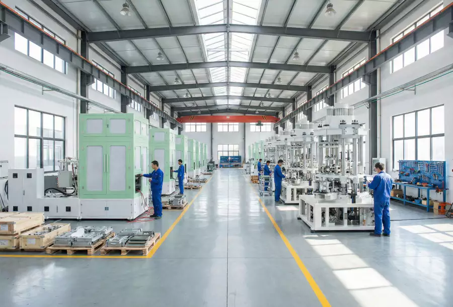
✔️ Work-area preparation
Remove loose tools, confirm guarding, clean mold and bottle-contact areas, and verify lifting devices are rated for the tooling being handled. Use a setup checklist signed by the responsible technician before energizing automatic motion.
✔️ Utilities
Confirm electrical supply, cooling water, chilled water where required, low-pressure air, blow air and material handling are connected to the correct ports. Check pressure, temperature, flow and leak condition at the machine connection rather than only at central plant equipment.
✔️ Safety circuit
Test emergency stops, doors, interlocks and safe manual modes using the machine procedure. Do not bypass an interlock to save setup time; correct the fault before motion testing.
Before Power-On: Verify Machine and Work Area
Work-area preparation
Work-area preparation. Remove loose tools, confirm guarding, clean mold and bottle-contact areas, and verify lifting devices are rated for the tooling being handled. Use a setup checklist signed by the responsible technician before energizing automatic motion. The step is complete only when work-area preparation produces the expected condition and the machine can proceed safely to the following operation. For repeatability, define who measures work-area preparation, where it is measured, and what bottle evidence is required before checking work-area preparation. Foreign objects, unsecured hoses or incorrect lifting can damage tooling before the process starts.
Itu ISBM replacement mold design reinforces the practical need to control mounting geometry, thermal behavior, transfer position, and cavity alignment rather than treating the mold as an isolated component.
Step 1: Confirm Utilities and Safety Circuits
Utilities
Utilities. Confirm electrical supply, cooling water, chilled water where required, low-pressure air, blow air and material handling are connected to the correct ports. Check pressure, temperature, flow and leak condition at the machine connection rather than only at central plant equipment. The step is complete only when utilities produces the expected condition and the machine can proceed safely to the following operation. Record the bottle response beside the setting or measurement for utilities; that record becomes the starting condition when utilities is reviewed. A utility that is nominally available can collapse under load because of undersized piping, closed valves or fouled strainers.
Step 2: Install and Inspect the Mold Package
Safety circuit
Safety circuit. Test emergency stops, doors, interlocks and safe manual modes using the machine procedure. Do not bypass an interlock to save setup time; correct the fault before motion testing. The step is complete only when safety circuit produces the expected condition and the machine can proceed safely to the following operation. If the symptom or performance target does not move as predicted, return safety circuit to the baseline and investigate safety circuit rather than stacking corrections. A defeated guard can turn a routine mold adjustment into a serious hazard.
Mold installation
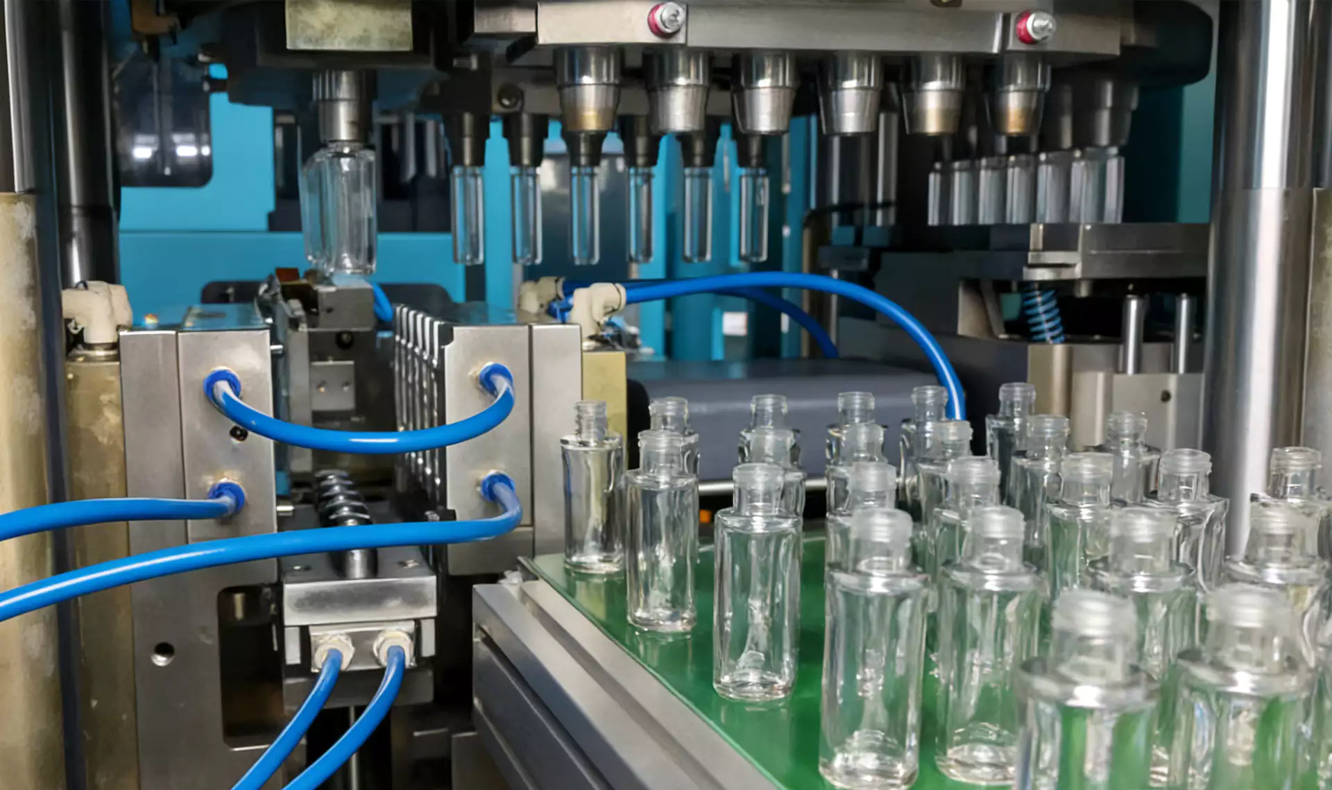
Mold installation. Clean mating surfaces, inspect fasteners and water connections, then install injection, lip/neck, conditioning and blow tooling in the required orientation. Use specified locating features and tightening procedure and verify no hose or cable can be pinched during index motion. The step is complete only when mold installation produces the expected condition and the machine can proceed safely to the following operation. If a change improves one region but worsens another, compare the material or energy movement between mold installation and mold installation instead of accepting the first visual improvement. Debris under a mold plate can create misalignment, flash or permanent damage.
Ketentuan kerja untuk tugas khusus ini
- Work-area preparation
- Remove loose tools, confirm guarding, clean mold and bottle-contact areas, and verify lifting devices are rated for the tooling being handled.
- Utilities
- Confirm electrical supply, cooling water, chilled water where required, low-pressure air, blow air and material handling are connected to the correct ports.
- Safety circuit
- Test emergency stops, doors, interlocks and safe manual modes using the machine procedure.
- Mold installation
- Clean mating surfaces, inspect fasteners and water connections, then install injection, lip/neck, conditioning and blow tooling in the required orientation.
Step 3: Prepare Resin and Material Handling
Cooling circuits
Cooling circuits. Connect each circuit to the intended manifold and purge trapped air. Confirm flow direction and return temperature for mold zones before heating resin. The step is complete only when cooling circuits produces the expected condition and the machine can proceed safely to the following operation. Where the outcome depends on material grade or tooling geometry, confirm the approved project limit and then use cooling circuits as the next cross-check. A blocked or crossed cooling line can create local hot spots that appear later as neck or base distortion.
| Barang | Pertanyaan teknik | Verifikasi praktis |
|---|---|---|
| Work-area preparation | Remove loose tools, confirm guarding, clean mold and bottle-contact areas, and verify lifting devices are rated for the tooling being handled. | Use a setup checklist signed by the responsible technician before energizing automatic motion. |
| Utilities | Confirm electrical supply, cooling water, chilled water where required, low-pressure air, blow air and material handling are connected to the correct ports. | Check pressure, temperature, flow and leak condition at the machine connection rather than only at central plant equipment. |
| Safety circuit | Test emergency stops, doors, interlocks and safe manual modes using the machine procedure. | Do not bypass an interlock to save setup time; correct the fault before motion testing. |
| Mold installation | Clean mating surfaces, inspect fasteners and water connections, then install injection, lip/neck, conditioning and blow tooling in the required orientation. | Use specified locating features and tightening procedure and verify no hose or cable can be pinched during index motion. |
| Cooling circuits | Connect each circuit to the intended manifold and purge trapped air. | Confirm flow direction and return temperature for mold zones before heating resin. |
| Resin preparation | Load the specified material after the dryer and conveying system have reached the resin supplier requirement. | Verify material identity, color, recycled-content blend and absence of mixed pellets in hopper and lines. |
| Kondisi rilis | Save the final recipe, note mold configuration, resin lot, utilities and any approved setup offsets. Record a golden sample and the startup checklist for the next changeover. | |
Step 4: Warm the Machine and Establish a Baseline
Resin preparation
Resin preparation. Load the specified material after the dryer and conveying system have reached the resin supplier requirement. Verify material identity, color, recycled-content blend and absence of mixed pellets in hopper and lines. The step is complete only when resin preparation produces the expected condition and the machine can proceed safely to the following operation. When the project is near a machine or material limit, require a molding trial that isolates resin preparation and then challenges resin preparation under the same bottle specification. Starting with wet or mixed resin makes process troubleshooting unreliable.
Step 5: Prove Manual Motions and Interlocks
Heat-up
Heat-up. Set barrel, hot-runner and mold-control temperatures from the validated baseline or supplier starting window, then allow thermal soak. Watch actual temperatures rather than starting as soon as setpoints first appear. The step is complete only when heat-up produces the expected condition and the machine can proceed safely to the following operation. The safest interpretation comes from comparing at least several stable cycles and then verifying heat-up without changing the rest of the recipe. Large metal masses can lag behind sensors; starting too early changes melt viscosity and part dimensions as the machine continues to heat.
Step 6: Start Injection and Inspect Preforms
Manual motion test
Manual motion test. Jog index, mold open/close, cores, stretch rods and take-out mechanisms at safe speed before automatic cycling. Confirm clearance at every extreme and check sensor status on the HMI. The step is complete only when manual motion test produces the expected condition and the machine can proceed safely to the following operation. A useful production trial keeps the resin lot and cavity identification fixed while manual motion test is changed, followed by a separate check of manual motion test. A reversed hose, wrong rod length or misinstalled insert may only become visible during motion.
Untuk topik ini, maka... portofolio mesin ISBM satu langkah menyediakan konteks peralatan yang berguna untuk menghubungkan persyaratan proses dengan platform resin-ke-botol terintegrasi.
Step 7: Add Conditioning, Stretch and Blow
Preform qualification
Preform qualification. Start injection at conservative validated settings and inspect mass, neck, gate, fill, flash, color and symmetry before enabling blowing. Stabilize the preform first; do not use blow settings to hide an injection defect. The step is complete only when preform qualification produces the expected condition and the machine can proceed safely to the following operation. The practical value of this check is that it turns preform qualification from a vague setting into evidence that can be compared with preform qualification. A bad preform makes every downstream adjustment ambiguous.
Stretch-blow introduction
Stretch-blow introduction. Enable conditioning and blow functions in a controlled sequence, then adjust rod timing, air timing and thermal profile from the approved baseline. Change one factor at a time and record bottle response by cavity. The step is complete only when stretch-blow introduction produces the expected condition and the machine can proceed safely to the following operation. Use this result to narrow the process window, not to create a new universal setpoint; the next constraint to confirm is stretch-blow introduction. Simultaneous large changes make it impossible to learn which variable fixed or created the defect.
Step 8: Validate Bottles Before Increasing Speed
Quality validation
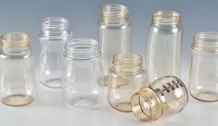
Quality validation. Check bottle weight, key dimensions, leak or functional tests, wall distribution and visual criteria over several cycles. Confirm all cavities, not just a best sample, and allow the process to reach thermal stability before signoff. The step is complete only when quality validation produces the expected condition and the machine can proceed safely to the following operation. The expected response should be visible in a bottle measurement, defect map, or machine trend before the team proceeds to quality validation. Early bottles may not represent steady-state production.
Step 9: Save the Recipe and Handover to Production
Recipe and handover
Recipe and handover. Save the final recipe, note mold configuration, resin lot, utilities and any approved setup offsets. Record a golden sample and the startup checklist for the next changeover. The step is complete only when recipe and handover produces the expected condition and the machine can proceed safely to the following operation. Once this check is stable, the next useful question is whether recipe and handover changes the same bottle region or affects a different part of the process. Without documented baseline conditions, each restart becomes a new experiment.
Quality validation: release evidence
Check bottle weight, key dimensions, leak or functional tests, wall distribution and visual criteria over several cycles. Confirm all cavities, not just a best sample, and allow the process to reach thermal stability before signoff. The condition is accepted only when the relevant bottle measurement or functional test remains stable after the process reaches normal operating temperature.
Recipe and handover: failure boundary
Without documented baseline conditions, each restart becomes a new experiment. Use that failure mode as the boundary for the trial and return to the previous stable condition when the bottle response moves in the wrong direction.
Itu Gambaran umum platform ISBM multi-material juga membantu menjelaskan bagaimana arsitektur mesin, material, utilitas, dan aplikasi botol saling berkaitan di tingkat lini produksi.
Questions that arise specifically in How to Set Up an ISBM Machine Step by Step
Should I start the blow stage before the preform is stable?
No. First establish consistent preform mass, neck and thermal condition so later bottle adjustments have a stable input.
What should be checked after a mold change?
Confirm tooling identity and orientation, locating surfaces, fasteners, cooling connections, sensors, stretch rods, take-out clearance and stored recipe before automatic cycling.
Why purge cooling circuits?
Trapped air reduces heat transfer and can create cavity-to-cavity or zone-to-zone temperature differences.
When can I increase cycle speed?
After the process is thermally stable and all cavities consistently pass agreed quality checks. Reduce time in small steps while monitoring the first defect that appears.
What should be saved with the recipe?
Machine settings are only part of the baseline. Also record mold revision, resin grade, utility conditions, cavity status and quality results.
Kesimpulan praktis
The working method for How to Set Up an ISBM Machine Step by Step is evidence first: establish work-area preparation, isolate the effect of heat-up, and use recipe and handover as the final production check. Foreign objects, unsecured hoses or incorrect lifting can damage tooling before the process starts.