
How to Control Preform Temperature in ISBM: Practical Technical Guide
The useful answer to How to Control Preform Temperature in ISBM comes from the interaction between thermal objective, localized cooling or heating, and control plan. The sections below turn those factors into checks that can be repeated on a production machine.
Thermal objectiveLocalized cooling or heatingControl plan
What this article must prove
Create and verify the preform temperature profile that allows material to stretch into the intended shoulder, sidewall and base without haze, pearlescence, local thinning or neck distortion. A defensible baseline begins with The body must be warm enough to stretch but not so soft that it loses controlled orientation or collapses before mold contact. The first verification method is Define the desired material movement by bottle region before changing heaters or cooling. From there, the article follows only checks that can materially change the answer promised by the title. Where an exact operating value depends on the resin grade, bottle drawing, mold, or delivered machine, the approved project specification controls the final setting.
✔️ Thermal objective
The body must be warm enough to stretch but not so soft that it loses controlled orientation or collapses before mold contact. Define the desired material movement by bottle region before changing heaters or cooling.
✔️ Measurement locations
Select fixed axial points such as below the neck, shoulder feed zone, mid-body feed zone and base-forming zone. Mark the measurement method, distance, emissivity setting if using infrared equipment, and time after transfer so readings can be reproduced.
✔️ Circumferential profile
Round bottles often seek symmetry, while oval or irregular bottles may need preferential heating or cooling. Compare corresponding positions around the preform and relate them to the thick and thin bottle panels.
For this topic, the one-step ISBM machine portfolio provides useful equipment context for connecting the process requirement to an integrated resin-to-bottle platform.
Why Preform Temperature Is a Profile, Not One Number
Thermal objective
Thermal objective. The body must be warm enough to stretch but not so soft that it loses controlled orientation or collapses before mold contact. Define the desired material movement by bottle region before changing heaters or cooling. Hold adjacent settings steady while testing thermal objective and verify the result with wall, dimension, or visual data. This item is considered resolved only when the finding remains repeatable after thermal stabilization and the next check, thermal objective, does not contradict it. Targeting a single arbitrary preform temperature can ignore the very gradient needed to form the bottle.
Map the Regions that Need Different Stretch Behavior
Measurement locations
Measurement locations. Select fixed axial points such as below the neck, shoulder feed zone, mid-body feed zone and base-forming zone. Mark the measurement method, distance, emissivity setting if using infrared equipment, and time after transfer so readings can be reproduced. Hold adjacent settings steady while testing measurement locations and verify the result with wall, dimension, or visual data. For repeatability, define who measures measurement locations, where it is measured, and what bottle evidence is required before checking measurement locations. Handheld measurements taken at random positions create data that cannot guide tuning.
Measure Temperature at Repeatable Locations
Circumferential profile
Circumferential profile. Round bottles often seek symmetry, while oval or irregular bottles may need preferential heating or cooling. Compare corresponding positions around the preform and relate them to the thick and thin bottle panels. Hold adjacent settings steady while testing circumferential profile and verify the result with wall, dimension, or visual data. Record the bottle response beside the setting or measurement for circumferential profile; that record becomes the starting condition when circumferential profile is reviewed. An apparently good axial average can hide circumferential imbalance that creates one thin wall.
Injection heat
Injection heat. Preform temperature begins with melt temperature, mold cooling, injection contact time and wall thickness. Stabilize injection conditions before attempting to correct everything in the conditioning station. Hold adjacent settings steady while testing injection heat and verify the result with wall, dimension, or visual data. If the symptom or performance target does not move as predicted, return injection heat to the baseline and investigate injection heat rather than stacking corrections. Thermal drift in the injection mold can make conditioning settings look unstable.
Working terms for this specific task
- Thermal objective
- The body must be warm enough to stretch but not so soft that it loses controlled orientation or collapses before mold contact.
- Measurement locations
- Select fixed axial points such as below the neck, shoulder feed zone, mid-body feed zone and base-forming zone.
- Circumferential profile
- Round bottles often seek symmetry, while oval or irregular bottles may need preferential heating or cooling.
- Injection heat
- Preform temperature begins with melt temperature, mold cooling, injection contact time and wall thickness.
Control Heat Left from Injection
Conditioning time
Conditioning time. Time between injection and blow allows heat to redistribute from the hotter wall interior toward the surface. Observe bottle changes when residence or index timing changes even if measured surface temperature looks similar. Hold adjacent settings steady while testing conditioning time and verify the result with wall, dimension, or visual data. If a change improves one region but worsens another, compare the material or energy movement between conditioning time and conditioning time instead of accepting the first visual improvement. Changing cycle time changes thermal history, so an old heating recipe may not work after a speed improvement.
| Articolo | Engineering question | Practical verification |
|---|---|---|
| Thermal objective | The body must be warm enough to stretch but not so soft that it loses controlled orientation or collapses before mold contact. | Define the desired material movement by bottle region before changing heaters or cooling. |
| Measurement locations | Select fixed axial points such as below the neck, shoulder feed zone, mid-body feed zone and base-forming zone. | Mark the measurement method, distance, emissivity setting if using infrared equipment, and time after transfer so readings can be reproduced. |
| Circumferential profile | Round bottles often seek symmetry, while oval or irregular bottles may need preferential heating or cooling. | Compare corresponding positions around the preform and relate them to the thick and thin bottle panels. |
| Injection heat | Preform temperature begins with melt temperature, mold cooling, injection contact time and wall thickness. | Stabilize injection conditions before attempting to correct everything in the conditioning station. |
| Conditioning time | Time between injection and blow allows heat to redistribute from the hotter wall interior toward the surface. | Observe bottle changes when residence or index timing changes even if measured surface temperature looks similar. |
| Localized cooling or heating | Use machine-specific conditioning zones to remove or add heat where material should stretch less or more. | Make small changes, then cut or measure bottles to see where material moved. |
| Release condition | Once the process is stable, record recipe values, measurement method, acceptable bottle map and utility conditions. Use trend limits or startup checks to detect drift before scrap increases. | |
Use Conditioning to Shape the Axial Profile
Localized cooling or heating
Localized cooling or heating. Use machine-specific conditioning zones to remove or add heat where material should stretch less or more. Make small changes, then cut or measure bottles to see where material moved. Hold adjacent settings steady while testing localized cooling or heating and verify the result with wall, dimension, or visual data. Where the outcome depends on material grade or tooling geometry, confirm the approved project limit and then use localized cooling or heating as the next cross-check. Large temperature corrections can relocate the defect rather than solve the overall distribution.
IL multi-material ISBM platform overview also helps frame how machine architecture, materials, utilities, and bottle applications fit together at line level.
Separate Surface Temperature from Through-Wall Condition
Neck protection
Neck protection. Keep the injection-molded neck finish dimensionally stable while conditioning the stretchable body. Monitor neck diameter, thread or snap features and sealing surface during thermal adjustments. Hold adjacent settings steady while testing neck protection and verify the result with wall, dimension, or visual data. When the project is near a machine or material limit, require a molding trial that isolates neck protection and then challenges neck protection under the same bottle specification. Excess heat near the finish can create closure problems unrelated to wall thickness.
Wall-thickness feedback
Wall-thickness feedback. Use a consistent thickness map around the bottle at several heights to judge thermal changes. Compare before and after profiles by cavity and mark where resin moved. Hold adjacent settings steady while testing wall-thickness feedback and verify the result with wall, dimension, or visual data. The safest interpretation comes from comparing at least several stable cycles and then verifying wall-thickness feedback without changing the rest of the recipe. Judging only bottle appearance can miss a dangerously thin panel or overloaded base.
Tune Temperature with Wall-Thickness Evidence
Visual defect feedback
Visual defect feedback. Haze, pearlescence, poor detail, base whitening and panel distortion can indicate the thermal/stretch combination is outside the useful window. Treat the symptom as evidence and verify with temperature and thickness data before adjusting multiple settings. Hold adjacent settings steady while testing visual defect feedback and verify the result with wall, dimension, or visual data. A useful production trial keeps the resin lot and cavity identification fixed while visual defect feedback is changed, followed by a separate check of visual defect feedback. The same visual defect can have more than one cause, so temperature should not be blamed automatically.
Lock the Window with a Repeatable Control Plan
Control plan
Control plan. Once the process is stable, record recipe values, measurement method, acceptable bottle map and utility conditions. Use trend limits or startup checks to detect drift before scrap increases. Hold adjacent settings steady while testing control plan and verify the result with wall, dimension, or visual data. The practical value of this check is that it turns control plan from a vague setting into evidence that can be compared with control plan. Without a repeatable measurement procedure, operators can gradually move away from the proven thermal window.
Visual defect feedback: release evidence
Haze, pearlescence, poor detail, base whitening and panel distortion can indicate the thermal/stretch combination is outside the useful window. Treat the symptom as evidence and verify with temperature and thickness data before adjusting multiple settings. The condition is accepted only when the relevant bottle measurement or functional test remains stable after the process reaches normal operating temperature.
Control plan: failure boundary
Without a repeatable measurement procedure, operators can gradually move away from the proven thermal window. Use that failure mode as the boundary for the trial and return to the previous stable condition when the bottle response moves in the wrong direction.
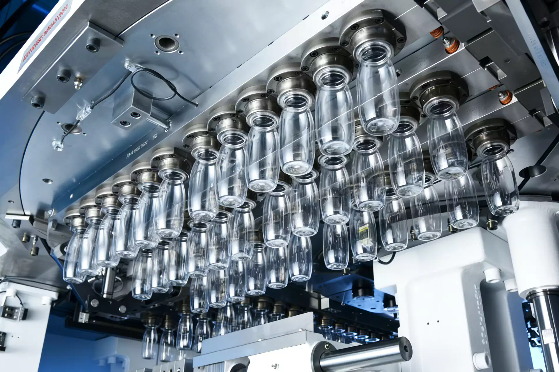
When translating the requirement into hardware, the HGY50-V3-EV machine configuration illustrates how injection, thermal conditioning, stretch-blow motion, and handling are organized on a compact one-step platform.
Questions that arise specifically in How to Control Preform Temperature in ISBM
Can I control preform temperature with one surface reading?
No. A single point does not describe axial, circumferential or through-wall gradients that control stretching.
Why does the same recipe behave differently after a cycle-time change?
Residence and heat-transfer time change with the cycle, so the preform can reach the blow station with a different internal temperature profile.
Should a colder zone become a thicker bottle wall?
Often less-stretchable material retains more thickness, but actual movement also depends on preform geometry, rod timing, air timing and neighboring zones.
How do I know whether temperature or stretch timing is the cause?
Use controlled experiments: hold the thermal profile constant while changing one timing variable, then compare the thickness map and defect location.
Why protect the neck from heat?
The neck finish is already injection molded to closure dimensions and generally should not participate in the body stretching process.
Practical conclusion
A robust answer to How to Control Preform Temperature in ISBM should survive a restart and a full thermal stabilization period. The setup record should therefore connect thermal objective with localized cooling or heating and the bottle result from control plan. Large temperature corrections can relocate the defect rather than solve the overall distribution.