Why Does Bottle Neck Deformation Occur in ISBM?: Practical Technical Guide
Why Does Bottle Neck Deformation Occur in ISBM? is a practical engineering question, so this guide starts with deformation type, moves through injection baseline, and ends with bottle-level verification rather than generic ISBM background.
Deformation typeBlow-mold alignmentCorrective sequence
Wat dit artikel moet bewijzen
Diagnose neck deformation by tracing heat exposure, lip-cavity cooling, transfer support, mold alignment, take-out force, closure torque and downstream handling. A defensible baseline begins with Identify ovality, thread flattening, tilted finish, seal-land warp, neck stretch or local dents. The first verification method is Measure critical diameters at several angles and heights. From there, the article follows only checks that can materially change the answer promised by the title. Where an exact operating value depends on the resin grade, bottle drawing, mold, or delivered machine, the approved project specification controls the final setting.

✔️ Deformation type
Identify ovality, thread flattening, tilted finish, seal-land warp, neck stretch or local dents. Measure critical diameters at several angles and heights.
✔️ Injection baseline
Inspect neck dimensions before the preform enters later stations. Compare molded preforms by cavity.
✔️ Lip cooling
Verify cooling flow, temperature and contact around the neck-holding components. Compare cavities for blocked circuits or warm zones.
Voor dit onderwerp, de ISBM-machineportfolio met éénstapsbediening Biedt nuttige context voor de apparatuur om de procesvereisten te koppelen aan een geïntegreerd platform van hars tot fles.
Define the Neck Deformation Precisely
Deformation type
Deformation type. Identify ovality, thread flattening, tilted finish, seal-land warp, neck stretch or local dents. Measure critical diameters at several angles and heights. The diagnostic test should show whether deformation type can physically create the observed defect before a repair or parameter change is accepted. Record the bottle response beside the setting or measurement for deformation type; that record becomes the starting condition when deformation type is reviewed. A visual description alone cannot distinguish thermal ovality from mechanical damage.
Check Whether the Finish Leaves Injection Correctly
Injection baseline
Injection baseline. Inspect neck dimensions before the preform enters later stations. Compare molded preforms by cavity. The diagnostic test should show whether injection baseline can physically create the observed defect before a repair or parameter change is accepted. If the symptom or performance target does not move as predicted, return injection baseline to the baseline and investigate injection baseline rather than stacking corrections. A neck formed incorrectly during injection cannot be fixed by extra cooling later.
Check Lip-Cavity and Neck Cooling
Lip cooling
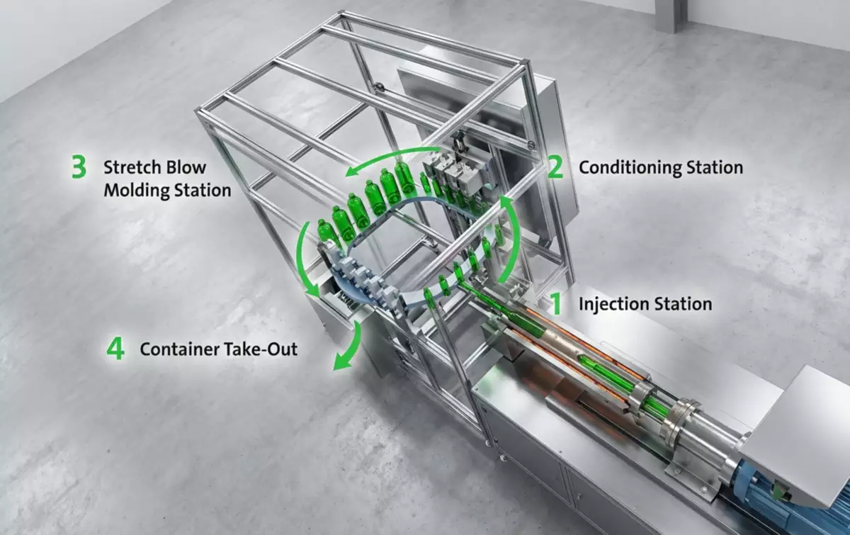
Lip cooling. Verify cooling flow, temperature and contact around the neck-holding components. Compare cavities for blocked circuits or warm zones. The diagnostic test should show whether lip cooling can physically create the observed defect before a repair or parameter change is accepted. If a change improves one region but worsens another, compare the material or energy movement between lip cooling and lip cooling instead of accepting the first visual improvement. Local loss of cooling can soften one side of the finish and create ovality.
Conditioning heat
Conditioning heat. Heat intended for the body can migrate into the finish. Review zone location, shielding and residence time after cycle or heater changes. The diagnostic test should show whether conditioning heat can physically create the observed defect before a repair or parameter change is accepted. Where the outcome depends on material grade or tooling geometry, confirm the approved project limit and then use conditioning heat as the next cross-check. A cycle-time change can expose the neck to a different thermal history even with unchanged setpoints.
Werkvoorwaarden voor deze specifieke taak
- Deformation type
- Identify ovality, thread flattening, tilted finish, seal-land warp, neck stretch or local dents.
- Injection baseline
- Inspect neck dimensions before the preform enters later stations.
- Lip cooling
- Verify cooling flow, temperature and contact around the neck-holding components.
- Conditioning heat
- Heat intended for the body can migrate into the finish.
Check Heat Migration during Conditioning
Transfer support
Transfer support. The neck holder should locate the preform without excessive force or wear. Inspect wear surfaces, alignment and clamping condition. The diagnostic test should show whether transfer support can physically create the observed defect before a repair or parameter change is accepted. When the project is near a machine or material limit, require a molding trial that isolates transfer support and then challenges transfer support under the same bottle specification. A hot neck can be deformed by a transfer mechanism that was harmless at lower temperature.
| Item | Technische vraag | Praktische verificatie |
|---|---|---|
| Deformation type | Identify ovality, thread flattening, tilted finish, seal-land warp, neck stretch or local dents. | Measure critical diameters at several angles and heights. |
| Injection baseline | Inspect neck dimensions before the preform enters later stations. | Compare molded preforms by cavity. |
| Lip cooling | Verify cooling flow, temperature and contact around the neck-holding components. | Compare cavities for blocked circuits or warm zones. |
| Conditioning heat | Heat intended for the body can migrate into the finish. | Review zone location, shielding and residence time after cycle or heater changes. |
| Transfer support | The neck holder should locate the preform without excessive force or wear. | Inspect wear surfaces, alignment and clamping condition. |
| Blow-mold alignment | Misalignment between neck holder and blow cavity can pull the finish during mold close or blow. | Check witness marks and mechanical centering. |
| Vrijgavevoorwaarde | Fix the stage where the neck first becomes incorrect, then revalidate closure fit. Keep body stretch settings unchanged unless they are the verified heat source. | |
Check Transfer and Mold Alignment
Blow-mold alignment
Blow-mold alignment. Misalignment between neck holder and blow cavity can pull the finish during mold close or blow. Check witness marks and mechanical centering. The diagnostic test should show whether blow-mold alignment can physically create the observed defect before a repair or parameter change is accepted. The safest interpretation comes from comparing at least several stable cycles and then verifying blow-mold alignment without changing the rest of the recipe. Repeated lateral load can create a tilted finish or uneven shoulder.
Bij het vertalen van de vereisten naar hardware, de HGY50-V3-EV machineconfiguratie Het illustreert hoe injectie, thermische conditionering, rek-blaasbeweging en handling georganiseerd zijn op een compact platform met één bewerkingsstap.
Check Ejection and Downstream Mechanical Load
Take-out
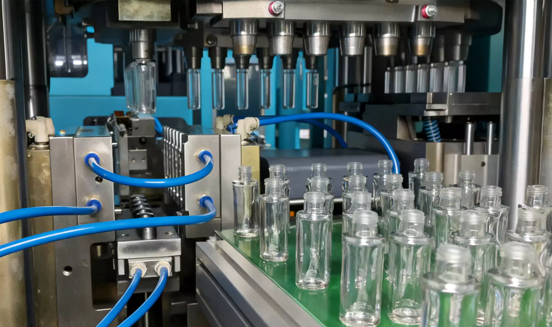
Take-out. Grippers or ejection devices may squeeze the finish while it is still warm. Observe slow-motion removal and check contact locations. The diagnostic test should show whether take-out can physically create the observed defect before a repair or parameter change is accepted. A useful production trial keeps the resin lot and cavity identification fixed while take-out is changed, followed by a separate check of take-out. The molding process may be correct while handling creates the final defect.
Downstream capping
Downstream capping. Excessive or misaligned closure application can be mistaken for molding deformation. Measure necks before and after the capper. The diagnostic test should show whether downstream capping can physically create the observed defect before a repair or parameter change is accepted. The practical value of this check is that it turns downstream capping from a vague setting into evidence that can be compared with downstream capping. Changing ISBM settings will not fix a capper chuck that is off-center.
Measure Closure-Critical Dimensions under Stable Production
Dimensional trend
Dimensional trend. Track critical neck dimensions by cavity over a long run. Correlate drift with mold temperature, water return and cycle changes. The diagnostic test should show whether dimensional trend can physically create the observed defect before a repair or parameter change is accepted. Use this result to narrow the process window, not to create a new universal setpoint; the next constraint to confirm is dimensional trend. A stable average can hide one cavity moving out of tolerance.
Correct the Heat or Mechanical Source, Not the Symptom
Corrective sequence
Corrective sequence. Fix the stage where the neck first becomes incorrect, then revalidate closure fit. Keep body stretch settings unchanged unless they are the verified heat source. The diagnostic test should show whether corrective sequence can physically create the observed defect before a repair or parameter change is accepted. The expected response should be visible in a bottle measurement, defect map, or machine trend before the team proceeds to corrective sequence. Compensating downstream for an upstream neck problem narrows the process window.
Dimensional trend: release evidence
Track critical neck dimensions by cavity over a long run. Correlate drift with mold temperature, water return and cycle changes. The condition is accepted only when the relevant bottle measurement or functional test remains stable after the process reaches normal operating temperature.
Corrective sequence: failure boundary
Compensating downstream for an upstream neck problem narrows the process window. Use that failure mode as the boundary for the trial and return to the previous stable condition when the bottle response moves in the wrong direction.
Voor beslissingen met betrekking tot gereedschap, ASB-12 vervangingsmatrijs engineering Dit benadrukt waarom dimensionale interfaces, koelaansluitingen, holtegeometrie en transferuitlijning als onderdeel van de machine-instelling moeten worden beschouwd.
Questions that arise specifically in Why Does Bottle Neck Deformation Occur in ISBM?
Why is the neck oval but the bottle body looks good?
The finish may be overheating or mechanically distorted in its own cooling/handling path while body forming remains stable.
Should the neck be reheated for stretching?
Normally the injection-molded finish is retained rather than stretched with the bottle body, so it should be protected from unnecessary heat.
How do I know if the capper is causing deformation?
Measure neck dimensions before and after closure application and inspect the direction of mechanical marks.
Why does only one cavity show neck warp?
Check that cavity or lip component for cooling blockage, wear, alignment or local heat exposure.
Can shorter cycle time cause neck deformation?
Yes indirectly. Changed residence and cooling time can alter the thermal state of the finish at later stations.
Praktische conclusie
The working method for Why Does Bottle Neck Deformation Occur in ISBM? is evidence first: establish deformation type, isolate the effect of blow-mold alignment, and use corrective sequence as the final production check. A visual description alone cannot distinguish thermal ovality from mechanical damage.