
How to Size an ISBM Machine for Your Bottle: Practical Technical Guide
How to Size an ISBM Machine for Your Bottle is a practical engineering question, so this guide starts with bottle envelope, moves through neck finish, and ends with bottle-level verification rather than generic ISBM background.
Bottle envelopeBlow mold spacingUtility sizing
Bu makalenin kanıtlaması gereken şey
Convert a bottle drawing and production requirement into machine envelope, injection, cavitation, stretch-blow and utility requirements. A defensible baseline begins with Use maximum body diameter or width, total height, neck finish, base projection and any handle or asymmetric feature. The first verification method is Mark the true maximum cross-section on the drawing and include mold wall, cooling and cavity spacing when converting bottle size into tooling envelope. From there, the article follows only checks that can materially change the answer promised by the title. Where an exact operating value depends on the resin grade, bottle drawing, mold, or delivered machine, the approved project specification controls the final setting.
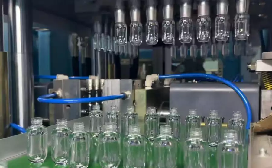
✔️ Bottle envelope
Use maximum body diameter or width, total height, neck finish, base projection and any handle or asymmetric feature. Mark the true maximum cross-section on the drawing and include mold wall, cooling and cavity spacing when converting bottle size into tooling envelope.
✔️ Neck finish
Record finish outer diameter, support ring, thread or snap geometry and any orientation requirement. Confirm lip-cavity and transfer clearances and whether the neck must remain indexed for an oval or handled bottle.
✔️ Preform geometry
Define preform mass, length, wall distribution, gate, inner diameter and stretchable length. Relate preform length to core and stretch-rod travel and verify removal clearances at injection and transfer.
Collect the Bottle Data that Controls Machine Size
Bottle envelope
Bottle envelope. Use maximum body diameter or width, total height, neck finish, base projection and any handle or asymmetric feature. Mark the true maximum cross-section on the drawing and include mold wall, cooling and cavity spacing when converting bottle size into tooling envelope. Use bottle envelope as a sizing constraint and confirm it against the complete machine movement and tooling envelope. When the project is near a machine or material limit, require a molding trial that isolates bottle envelope and then challenges bottle envelope under the same bottle specification. Using nominal volume as a proxy for physical size can select a machine that cannot close or transfer the mold safely.
O ASB uyumlu takım konfigürasyonu Bu durum, kalıp arayüzlerinin ve makine hareketinin değiştirme, sorun giderme veya kapasite değişiklikleri sırasında nasıl uyumlu kalması gerektiğinin kontrol edilmesi açısından da önemlidir.
Convert Bottle Geometry into Mold Envelope
Neck finish
Neck finish. Record finish outer diameter, support ring, thread or snap geometry and any orientation requirement. Confirm lip-cavity and transfer clearances and whether the neck must remain indexed for an oval or handled bottle. Use neck finish as a sizing constraint and confirm it against the complete machine movement and tooling envelope. The safest interpretation comes from comparing at least several stable cycles and then verifying neck finish without changing the rest of the recipe. Neck geometry can limit cavitation even when the body is small.
Preform geometry
Preform geometry. Define preform mass, length, wall distribution, gate, inner diameter and stretchable length. Relate preform length to core and stretch-rod travel and verify removal clearances at injection and transfer. Use preform geometry as a sizing constraint and confirm it against the complete machine movement and tooling envelope. A useful production trial keeps the resin lot and cavity identification fixed while preform geometry is changed, followed by a separate check of preform geometry. An excessively long or thick preform may be difficult to cool and condition within the desired cycle.
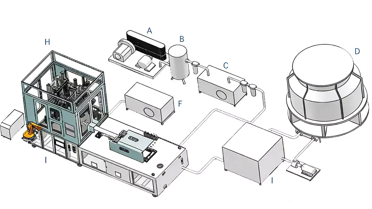
Calculate Shot and Plasticizing Demand
Shot demand
Shot demand. Multiply preform mass by cavity count and include the actual injection system configuration. Compare total shot with the machine injection capacity and required recovery time using the supplier calculation. Use shot demand as a sizing constraint and confirm it against the complete machine movement and tooling envelope. The practical value of this check is that it turns shot demand from a vague setting into evidence that can be compared with shot demand. Running at the edge of injection capacity can reduce process margin or extend the cycle.
Bu özel görev için çalışma koşulları
- Bottle envelope
- Use maximum body diameter or width, total height, neck finish, base projection and any handle or asymmetric feature.
- Neck finish
- Record finish outer diameter, support ring, thread or snap geometry and any orientation requirement.
- Preform geometry
- Define preform mass, length, wall distribution, gate, inner diameter and stretchable length.
- Shot demand
- Multiply preform mass by cavity count and include the actual injection system configuration.
Check Stretch Length and Blow Space
Plasticizing rate
Plasticizing rate. Estimate resin mass processed per hour from good output plus expected scrap and startup consumption. Check that the screw can recover the next shot without becoming the cycle bottleneck and without excessive residence time. Use plasticizing rate as a sizing constraint and confirm it against the complete machine movement and tooling envelope. Use this result to narrow the process window, not to create a new universal setpoint; the next constraint to confirm is plasticizing rate. A screw sized only for maximum throughput may be poorly matched to low-cavity jobs, while an undersized unit extends recovery.
Blow mold spacing
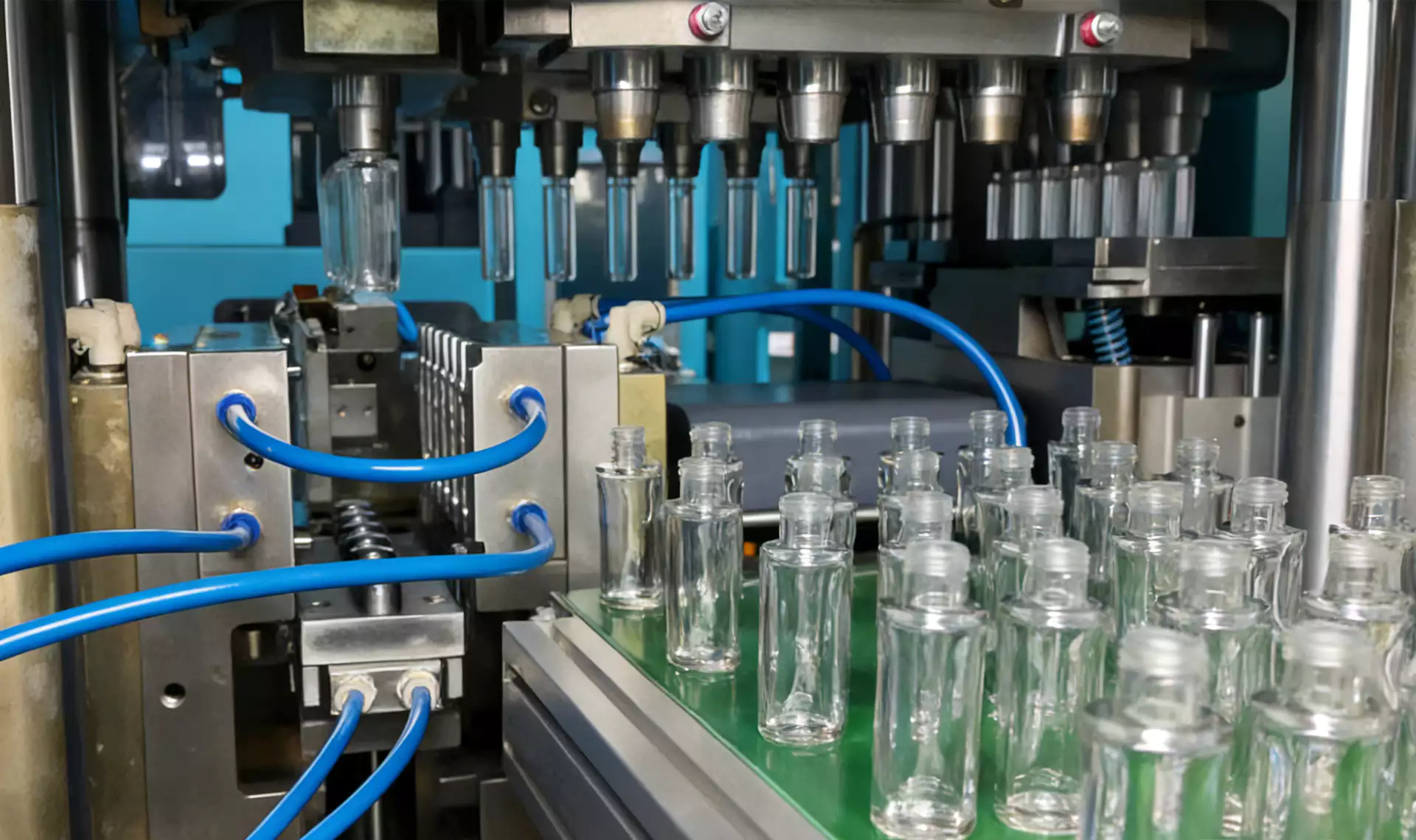
Blow mold spacing. Lay out cavity pitch using the widest bottle section, mold split, cooling channels, clamp structure and venting needs. Check interference during mold opening, bottle removal and turntable transfer, not only when the mold is closed. Use blow mold spacing as a sizing constraint and confirm it against the complete machine movement and tooling envelope. The expected response should be visible in a bottle measurement, defect map, or machine trend before the team proceeds to blow mold spacing. A layout that fits statically may collide during motion.
| Öğe | Mühendislik sorusu | Pratik doğrulama |
|---|---|---|
| Bottle envelope | Use maximum body diameter or width, total height, neck finish, base projection and any handle or asymmetric feature. | Mark the true maximum cross-section on the drawing and include mold wall, cooling and cavity spacing when converting bottle size into tooling envelope. |
| Neck finish | Record finish outer diameter, support ring, thread or snap geometry and any orientation requirement. | Confirm lip-cavity and transfer clearances and whether the neck must remain indexed for an oval or handled bottle. |
| Preform geometry | Define preform mass, length, wall distribution, gate, inner diameter and stretchable length. | Relate preform length to core and stretch-rod travel and verify removal clearances at injection and transfer. |
| Shot demand | Multiply preform mass by cavity count and include the actual injection system configuration. | Compare total shot with the machine injection capacity and required recovery time using the supplier calculation. |
| Plasticizing rate | Estimate resin mass processed per hour from good output plus expected scrap and startup consumption. | Check that the screw can recover the next shot without becoming the cycle bottleneck and without excessive residence time. |
| Blow mold spacing | Lay out cavity pitch using the widest bottle section, mold split, cooling channels, clamp structure and venting needs. | Check interference during mold opening, bottle removal and turntable transfer, not only when the mold is closed. |
| Serbest bırakma koşulu | Translate the chosen machine and cycle into compressor, electrical, chiller, cooling-water and dryer demand. Verify both average load and short-duration peak demand at the machine connection. | |
Determine Feasible Cavitation
Stretch travel
Stretch travel. Compare the stretchable preform length and final bottle base position with available rod stroke and timing control. Confirm where the rod starts, when it contacts the preform base and where it finishes relative to the bottle base insert. Use stretch travel as a sizing constraint and confirm it against the complete machine movement and tooling envelope. Once this check is stable, the next useful question is whether stretch travel changes the same bottle region or affects a different part of the process. Insufficient or poorly controlled travel produces material-distribution problems that pressure changes cannot fully correct.
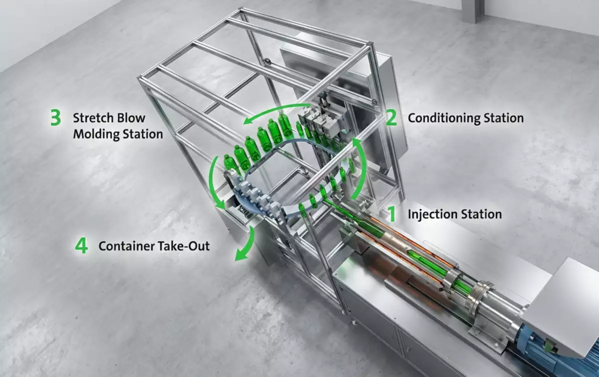
Check Cycle and Output Together
Cavity count
Cavity count. Test several cavity counts because machine envelope, shot mass and cycle time interact. For each count, calculate good bottles per hour and tooling cost, then identify the least-cost configuration that meets demand. Use cavity count as a sizing constraint and confirm it against the complete machine movement and tooling envelope. This checkpoint should be evaluated before cavity count is altered, because otherwise two process mechanisms change at the same time. More cavities can increase mold cost and cooling load without proportional output if injection or cooling time rises.
Bu konu için, tek adımlı ISBM makine portföyü Bu, proses gereksinimini entegre bir reçine-şişeleme platformuna bağlamak için faydalı ekipman bağlamı sağlar.
Output margin
Output margin. Use saleable output and an operating schedule rather than theoretical cycles per hour. Model startup, mold changes, planned maintenance and normal minor stops to verify monthly capacity. Use output margin as a sizing constraint and confirm it against the complete machine movement and tooling envelope. For this topic, the engineering log should connect output margin with the observed bottle condition and then test whether output margin supports the same diagnosis. A machine sized to average demand with no scheduling margin can create chronic overtime or missed deliveries.
Verify Utilities and Handling Before Final Sizing
Utility sizing
Utility sizing. Translate the chosen machine and cycle into compressor, electrical, chiller, cooling-water and dryer demand. Verify both average load and short-duration peak demand at the machine connection. Use utility sizing as a sizing constraint and confirm it against the complete machine movement and tooling envelope. Do not judge this factor from the HMI value alone; pair it with the actual bottle result, then continue with utility sizing only after the relationship is clear. Undersized distribution piping or chiller capacity can make a correctly sized molding machine behave as if it were undersized.
Output margin: release evidence
Use saleable output and an operating schedule rather than theoretical cycles per hour. Model startup, mold changes, planned maintenance and normal minor stops to verify monthly capacity. The condition is accepted only when the relevant bottle measurement or functional test remains stable after the process reaches normal operating temperature.
Utility sizing: failure boundary
Undersized distribution piping or chiller capacity can make a correctly sized molding machine behave as if it were undersized. Use that failure mode as the boundary for the trial and return to the previous stable condition when the bottle response moves in the wrong direction.
Sizing equations to put on the project sheet
Required good output per hour = planned good bottles / available production hours. Available hours should already exclude the downtime that the production plan deliberately reserves for mold changes and maintenance. Do not divide annual demand by all calendar hours unless the plant actually runs continuously.
Shot mass = preform mass per cavity × active cavities, adjusted for the actual injection system and any material that is not part of the finished preforms. Theoretical bottle output = active cavities × 3,600 / stable cycle time in seconds. Practical capacity then applies yield and availability to that theoretical number.
Use these equations to compare candidate cavitation and machine sizes, but verify the final shot-utilization, plasticizing, clamp, cooling, and stretch-blow limits with the delivered machine and mold data.
O ISBM yedek kalıp tasarımı Bu durum, kalıbı izole bir bileşen olarak ele almak yerine, montaj geometrisini, termal davranışı, transfer konumunu ve boşluk hizalamasını kontrol etmenin pratik gerekliliğini pekiştirir.
Questions that arise specifically in How to Size an ISBM Machine for Your Bottle
What bottle dimension usually limits machine size?
There is no single answer. Maximum body width, height, neck finish, preform length, shot mass, mold pitch or stretch travel can become the controlling limit.
Can I size the machine from bottle volume alone?
No. Two bottles with the same volume can require very different mold envelopes and preform designs.
How should I size for several bottle formats?
Create one sizing sheet per format, then choose a machine that satisfies the controlling requirement of every format with reasonable process margin.
Should maximum machine capacity equal my target output?
No. Compare good output under the expected cycle and operating schedule. Nameplate limits are not the same as sustainable production.
Why does cavitation affect machine size?
Cavitation multiplies shot mass and mold width while also changing cooling, clamp, air demand and the economics of each cycle.
Pratik sonuç
The working method for How to Size an ISBM Machine for Your Bottle is evidence first: establish bottle envelope, isolate the effect of blow mold spacing, and use utility sizing as the final production check. Using nominal volume as a proxy for physical size can select a machine that cannot close or transfer the mold safely.