How to Mold Oval and Irregular Bottles with ISBM: Practical Technical Guide
How to Mold Oval and Irregular Bottles with ISBM is a practical engineering question, so this guide starts with directional map, moves through orientation index, and ends with bottle-level verification rather than generic ISBM background.
Directional mapVentingRecipe lock
本文必须证明什么
Mold oval and irregular containers by controlling preform rotational orientation, preferential heating or cooling, directional stretch, blow timing, cavity venting and wall-thickness verification. A defensible baseline begins with Mark bottle major axis, minor axis, deep corners, recessed grips and high-surface-area panels. The first verification method is Relate each bottle region to the corresponding preform circumference. From there, the article follows only checks that can materially change the answer promised by the title. Where an exact operating value depends on the resin grade, bottle drawing, mold, or delivered machine, the approved project specification controls the final setting.
✔️ Directional map
Mark bottle major axis, minor axis, deep corners, recessed grips and high-surface-area panels. Relate each bottle region to the corresponding preform circumference.
✔️ Orientation index
Use a neck, gate, handling or tooling feature that keeps the preform angular position repeatable. Check orientation at injection release, conditioning and blow station.
✔️ Preferential temperature
Make high-expansion regions more stretchable and low-expansion regions more resistant within the resin process window. Adjust directional heating/cooling in small increments and cut bottles after each change.
对于与刀具相关的决策, ASB-12 替换模具工程 重点阐述了为什么尺寸接口、冷却连接、腔体几何形状和传输对准必须作为机器设置的一部分来处理。
Step 1: Map the Long and Short Stretch Directions
Directional map
Directional map. Mark bottle major axis, minor axis, deep corners, recessed grips and high-surface-area panels. Relate each bottle region to the corresponding preform circumference. The step is complete only when directional map produces the expected condition and the machine can proceed safely to the following operation. For this topic, the engineering log should connect directional map with the observed bottle condition and then test whether directional map supports the same diagnosis. Without a material map, operators may heat the wrong side of the preform.
Step 2: Create an Orientation Feature that Cannot Drift
Orientation index
Orientation index. Use a neck, gate, handling or tooling feature that keeps the preform angular position repeatable. Check orientation at injection release, conditioning and blow station. The step is complete only when orientation index produces the expected condition and the machine can proceed safely to the following operation. Do not judge this factor from the HMI value alone; pair it with the actual bottle result, then continue with orientation index only after the relationship is clear. A few degrees of drift can rotate thick material away from the long-stretch panel.
Step 3: Build the Circumferential Thermal Profile
Preferential temperature
Preferential temperature. Make high-expansion regions more stretchable and low-expansion regions more resistant within the resin process window. Adjust directional heating/cooling in small increments and cut bottles after each change. The step is complete only when preferential temperature produces the expected condition and the machine can proceed safely to the following operation. Keep preferential temperature at its validated baseline while this item is tested so the bottle response can be attributed to one cause. Excess preferential heating can create local haze or weak thin walls.
Rod motion
Rod motion. Use axial stretch to move material toward the lower bottle before the large radial difference develops. Tune rod timing with pre-blow while watching major/minor thickness. The step is complete only when rod motion produces the expected condition and the machine can proceed safely to the following operation. Use the smallest controlled change that can prove the effect of rod motion, then restore the baseline before a different adjustment such as rod motion is tried. Too-early radial expansion tends to amplify circumferential imbalance.
这项特定任务的工作条款
- Directional map
- Mark bottle major axis, minor axis, deep corners, recessed grips and high-surface-area panels.
- Orientation index
- Use a neck, gate, handling or tooling feature that keeps the preform angular position repeatable.
- Preferential temperature
- Make high-expansion regions more stretchable and low-expansion regions more resistant within the resin process window.
- Rod motion
- Use axial stretch to move material toward the lower bottle before the large radial difference develops.
Step 4: Synchronize Stretch Rod and Pre-Blow
Pre-blow
Pre-blow. Establish a controlled bubble that does not contact one side of the mold prematurely. Observe whether the expanding preform leans, folds or touches the cavity asymmetrically. The step is complete only when pre-blow produces the expected condition and the machine can proceed safely to the following operation. This factor belongs in the setup sheet because it directly changes the conditions under which pre-blow is evaluated. Early unilateral contact freezes material and makes later pressure ineffective.
| 物品 | 工程问题 | 实际验证 |
|---|---|---|
| Directional map | Mark bottle major axis, minor axis, deep corners, recessed grips and high-surface-area panels. | Relate each bottle region to the corresponding preform circumference. |
| Orientation index | Use a neck, gate, handling or tooling feature that keeps the preform angular position repeatable. | Check orientation at injection release, conditioning and blow station. |
| Preferential temperature | Make high-expansion regions more stretchable and low-expansion regions more resistant within the resin process window. | Adjust directional heating/cooling in small increments and cut bottles after each change. |
| Rod motion | Use axial stretch to move material toward the lower bottle before the large radial difference develops. | Tune rod timing with pre-blow while watching major/minor thickness. |
| Pre-blow | Establish a controlled bubble that does not contact one side of the mold prematurely. | Observe whether the expanding preform leans, folds or touches the cavity asymmetrically. |
| Venting | Deep corners and flat panels can trap air. | Keep vents clean at corner ends, parting lines and base features. |
| 发布条件 | Save orientation settings, thermal zones, rod motion, air timing and mold temperatures as one validated recipe. Create a startup check that confirms orientation before full-speed production. | |
Step 5: Vent Deep Corners and Recesses
Venting
Venting. Deep corners and flat panels can trap air. Keep vents clean at corner ends, parting lines and base features. The step is complete only when venting produces the expected condition and the machine can proceed safely to the following operation. If the result differs by cavity, compare the local hardware related to venting before moving on to venting. Trapped air can cause dull spots, incomplete detail or local overheating.
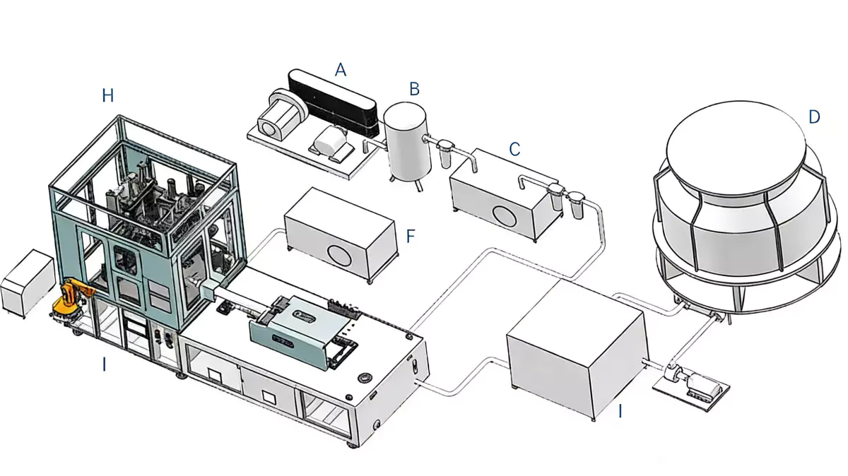
在将需求转化为硬件时, HGY50-V3-EV整机配置 图示了注射、热处理、拉伸吹塑运动和搬运如何在紧凑的一步式平台上进行组织。
Step 6: Control Parting Line and Panel Cooling
Mold cooling
Mold cooling. Large flat panels and narrow edges can cool at different rates. Balance circuits and compare panel flatness after stabilization. The step is complete only when mold cooling produces the expected condition and the machine can proceed safely to the following operation. This item is considered resolved only when the finding remains repeatable after thermal stabilization and the next check, mold cooling, does not contradict it. Uneven cooling can create twist or panel oil-canning even with good wall thickness.
Thickness by angle
Thickness by angle. Measure at consistent angular positions around several bottle heights. Report major-axis, minor-axis and corner values separately. The step is complete only when thickness by angle produces the expected condition and the machine can proceed safely to the following operation. For repeatability, define who measures thickness by angle, where it is measured, and what bottle evidence is required before checking thickness by angle. An average circumferential thickness can hide a dangerous local minimum.
Step 7: Measure Wall Thickness by Angle
Visual alignment
Visual alignment. Logos, embossing and label panels may require the neck or gate to align with the bottle face. Verify orientation repeatability during normal automatic running and after stops. The step is complete only when visual alignment produces the expected condition and the machine can proceed safely to the following operation. Record the bottle response beside the setting or measurement for visual alignment; that record becomes the starting condition when visual alignment is reviewed. An orientation system that only works during slow setup is not production capable.
Step 8: Lock Orientation and Recipe Controls
Recipe lock
Recipe lock. Save orientation settings, thermal zones, rod motion, air timing and mold temperatures as one validated recipe. Create a startup check that confirms orientation before full-speed production. The step is complete only when recipe lock produces the expected condition and the machine can proceed safely to the following operation. If the symptom or performance target does not move as predicted, return recipe lock to the baseline and investigate recipe lock rather than stacking corrections. A correct thermal recipe is useless if the preform enters the blow mold rotated.
Visual alignment: release evidence
Logos, embossing and label panels may require the neck or gate to align with the bottle face. Verify orientation repeatability during normal automatic running and after stops. The condition is accepted only when the relevant bottle measurement or functional test remains stable after the process reaches normal operating temperature.
Recipe lock: failure boundary
A correct thermal recipe is useless if the preform enters the blow mold rotated. Use that failure mode as the boundary for the trial and return to the previous stable condition when the bottle response moves in the wrong direction.
这 ASB-12 injection tooling replacement is a useful equipment example when the task involves mold exchange, dimensional matching, cooling performance, or repeatable transfer between ISBM stations.
Questions that arise specifically in How to Mold Oval and Irregular Bottles with ISBM
Why do oval bottles get thin on one side?
The major direction requires more radial stretch. If temperature and orientation are uniform, material can over-stretch there while remaining heavy on the short side.
How do I keep preferential heating aligned?
Use a repeatable preform orientation/indexing method and verify angular position through every transfer stage.
Can higher blow pressure correct directional thinning?
No. Once the material has stretched and contacted the mold, pressure cannot redistribute it effectively.
How should thickness be measured?
Measure several heights and fixed angular positions, especially major axis, minor axis, corners and grip features.
Why does an oval bottle twist after molding?
Check circumferential wall imbalance, mold cooling, residual stress, orientation drift and hot downstream handling.
实际结论
The working method for How to Mold Oval and Irregular Bottles with ISBM is evidence first: establish directional map, isolate the effect of venting, and use recipe lock as the final production check. Without a material map, operators may heat the wrong side of the preform.