
How to Calculate Stretch Ratio in ISBM Molding: Practical Technical Guide
For How to Calculate Stretch Ratio in ISBM Molding, the objective is not to find one universal setting. It is to prove which combination of reference length, axial ratio, and material distribution produces the required bottle under stable factory conditions.
Reference lengthHoop ratioDesign iteration
What this article must prove
Calculate axial, hoop and overall stretch ratio from preform and bottle geometry, interpret what the numbers mean, and use them as design inputs rather than as universal pass/fail limits. A defensible baseline begins with Use only the preform body length that actually stretches, excluding the neck finish and non-stretched support region. The first verification method is Measure from the effective transition below the neck holder to the preform base region that becomes the bottle base. From there, the article follows only checks that can materially change the answer promised by the title. Where an exact operating value depends on the resin grade, bottle drawing, mold, or delivered machine, the approved project specification controls the final setting.
✔️ Reference length
Use only the preform body length that actually stretches, excluding the neck finish and non-stretched support region. Measure from the effective transition below the neck holder to the preform base region that becomes the bottle base.
✔️ Bottle stretch length
Define the final axial distance occupied by the stretched preform material, again excluding the retained neck. Use the bottle drawing and identify where the same material begins and ends after forming.
✔️ Axial ratio
Calculate axial stretch ratio as final stretchable bottle length divided by initial stretchable preform length. Keep the same length units in numerator and denominator and report the geometric basis with the result.
Define the Stretchable Length and Diameter Correctly
Reference length
Reference length. Use only the preform body length that actually stretches, excluding the neck finish and non-stretched support region. Measure from the effective transition below the neck holder to the preform base region that becomes the bottle base. Write the units, measurement points, formula basis, and interpretation used for reference length so another engineer can reproduce the calculation. This factor belongs in the setup sheet because it directly changes the conditions under which reference length is evaluated. Using overall preform length overstates the denominator and produces a misleading axial ratio.
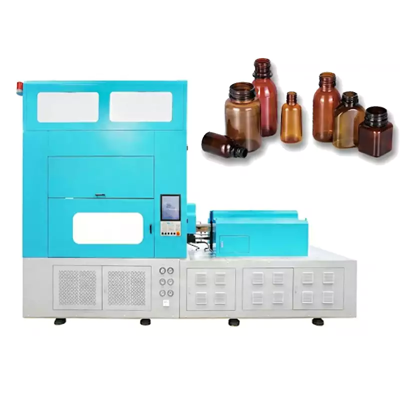
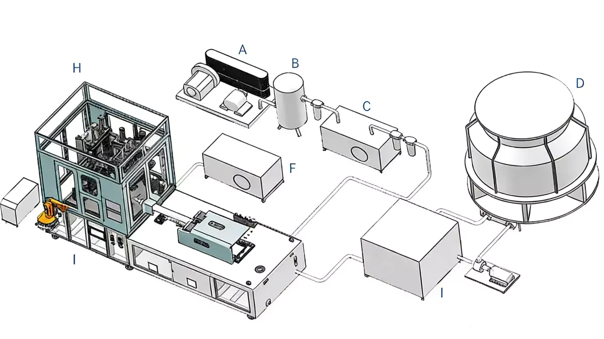
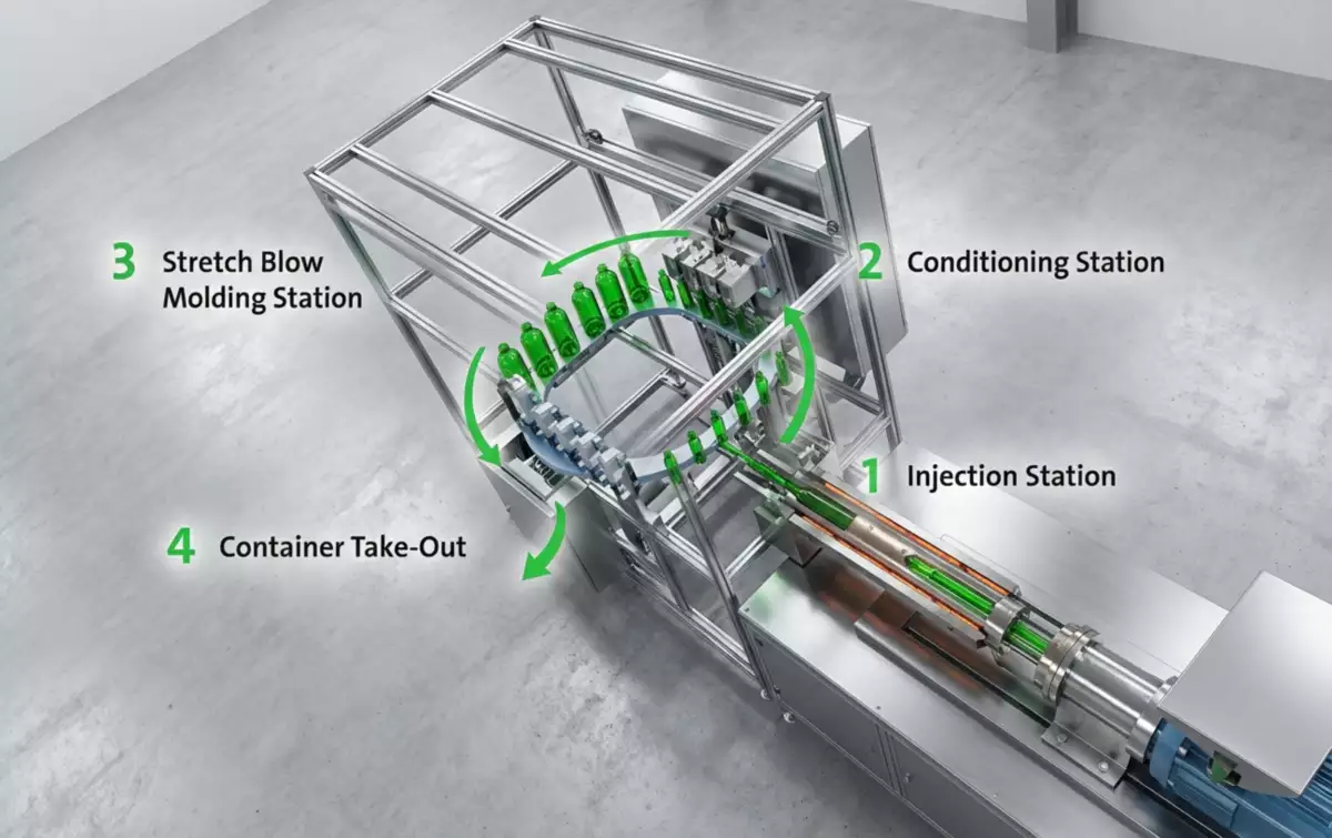
The multi-material ISBM platform overview also helps frame how machine architecture, materials, utilities, and bottle applications fit together at line level.
Calculate Axial Stretch Ratio
Bottle stretch length
Bottle stretch length. Define the final axial distance occupied by the stretched preform material, again excluding the retained neck. Use the bottle drawing and identify where the same material begins and ends after forming. Write the units, measurement points, formula basis, and interpretation used for bottle stretch length so another engineer can reproduce the calculation. If the result differs by cavity, compare the local hardware related to bottle stretch length before moving on to bottle stretch length. Including neck height makes different neck finishes appear to change stretch behavior even when the body is identical.
Axial ratio
Axial ratio. Calculate axial stretch ratio as final stretchable bottle length divided by initial stretchable preform length. Keep the same length units in numerator and denominator and report the geometric basis with the result. Write the units, measurement points, formula basis, and interpretation used for axial ratio so another engineer can reproduce the calculation. This item is considered resolved only when the finding remains repeatable after thermal stabilization and the next check, axial ratio, does not contradict it. A ratio without clearly defined reference points cannot be reproduced.
Calculate Hoop Stretch Ratio
Preform diameter
Preform diameter. Choose the relevant outside diameter of the stretchable preform body, recognizing that tapered preforms may need a more detailed analysis. Document whether the comparison uses outside diameter, mean diameter or a local section. Write the units, measurement points, formula basis, and interpretation used for preform diameter so another engineer can reproduce the calculation. For repeatability, define who measures preform diameter, where it is measured, and what bottle evidence is required before checking preform diameter. Using a single diameter for a strongly tapered preform can hide local over-stretch risk.
Working terms for this specific task
- Reference length
- Use only the preform body length that actually stretches, excluding the neck finish and non-stretched support region.
- Bottle stretch length
- Define the final axial distance occupied by the stretched preform material, again excluding the retained neck.
- Axial ratio
- Calculate axial stretch ratio as final stretchable bottle length divided by initial stretchable preform length.
- Preform diameter
- Choose the relevant outside diameter of the stretchable preform body, recognizing that tapered preforms may need a more detailed analysis.
Combine the Ratios for an Overall View
Bottle diameter
Bottle diameter. For a round bottle use the corresponding body diameter; for an oval bottle treat major and minor directions separately. Calculate directional hoop expansion where the shape is asymmetric. Write the units, measurement points, formula basis, and interpretation used for bottle diameter so another engineer can reproduce the calculation. Record the bottle response beside the setting or measurement for bottle diameter; that record becomes the starting condition when bottle diameter is reviewed. One average diameter can conceal a thin major-axis panel.
Hoop ratio
Hoop ratio. Calculate hoop stretch ratio as final local bottle diameter divided by initial local preform diameter for the compared region. Use matched axial locations or a material-mapping model when the geometry changes strongly. Write the units, measurement points, formula basis, and interpretation used for hoop ratio so another engineer can reproduce the calculation. If the symptom or performance target does not move as predicted, return hoop ratio to the baseline and investigate hoop ratio rather than stacking corrections. Mismatched sections produce a number that has little physical meaning.
| Item | Engineering question | Practical verification |
|---|---|---|
| Reference length | Use only the preform body length that actually stretches, excluding the neck finish and non-stretched support region. | Measure from the effective transition below the neck holder to the preform base region that becomes the bottle base. |
| Bottle stretch length | Define the final axial distance occupied by the stretched preform material, again excluding the retained neck. | Use the bottle drawing and identify where the same material begins and ends after forming. |
| Axial ratio | Calculate axial stretch ratio as final stretchable bottle length divided by initial stretchable preform length. | Keep the same length units in numerator and denominator and report the geometric basis with the result. |
| Preform diameter | Choose the relevant outside diameter of the stretchable preform body, recognizing that tapered preforms may need a more detailed analysis. | Document whether the comparison uses outside diameter, mean diameter or a local section. |
| Bottle diameter | For a round bottle use the corresponding body diameter; for an oval bottle treat major and minor directions separately. | Calculate directional hoop expansion where the shape is asymmetric. |
| Hoop ratio | Calculate hoop stretch ratio as final local bottle diameter divided by initial local preform diameter for the compared region. | Use matched axial locations or a material-mapping model when the geometry changes strongly. |
| Release condition | Compare several preform lengths, diameters and mass distributions before finalizing tooling. Use calculations to screen concepts, then validate the chosen geometry with simulation or molding trials. | |
Worked Example with Hypothetical Dimensions
Overall ratio
Overall ratio. A common geometric indicator multiplies axial and hoop stretch ratios to describe approximate biaxial area expansion. Use it as a comparison tool alongside material supplier guidance and trial data. Write the units, measurement points, formula basis, and interpretation used for overall ratio so another engineer can reproduce the calculation. If a change improves one region but worsens another, compare the material or energy movement between overall ratio and overall ratio instead of accepting the first visual improvement. It is not a universal specification because resin grade, temperature, thickness and bottle geometry change the workable range.
Use Ratios to Compare Preform Concepts
Worked example
Worked example. For illustration, if a hypothetical stretchable preform length is 70 mm and the corresponding bottle body length is 210 mm, the axial ratio is 3.0. If a local preform diameter is 25 mm and the bottle diameter is 75 mm, the hoop ratio is 3.0 and the simple combined ratio is 9.0. Treat these numbers only as an arithmetic example, not as recommended values for a real resin or bottle. Write the units, measurement points, formula basis, and interpretation used for worked example so another engineer can reproduce the calculation. Where the outcome depends on material grade or tooling geometry, confirm the approved project limit and then use worked example as the next cross-check. Copying example ratios into a design without material validation can create poor orientation or impossible wall distribution.
For tooling-related decisions, the ASB-12 replacement mold engineering highlights why dimensional interfaces, cooling connections, cavity geometry, and transfer alignment must be treated as part of the machine setup.
Material distribution
Material distribution. Use thickness mapping to see whether the calculated geometry actually produces balanced draw. Compare shoulder, panel, heel and base thickness with the predicted stretch demand. Write the units, measurement points, formula basis, and interpretation used for material distribution so another engineer can reproduce the calculation. When the project is near a machine or material limit, require a molding trial that isolates material distribution and then challenges material distribution under the same bottle specification. A nominally reasonable ratio can still produce local thin zones where the shape changes abruptly.
Why Stretch Ratio Alone Cannot Guarantee a Good Bottle
Design iteration
Design iteration. Compare several preform lengths, diameters and mass distributions before finalizing tooling. Use calculations to screen concepts, then validate the chosen geometry with simulation or molding trials. Write the units, measurement points, formula basis, and interpretation used for design iteration so another engineer can reproduce the calculation. The safest interpretation comes from comparing at least several stable cycles and then verifying design iteration without changing the rest of the recipe. Stretch-ratio calculation is a design filter, not a substitute for physical validation.
Material distribution: release evidence
Use thickness mapping to see whether the calculated geometry actually produces balanced draw. Compare shoulder, panel, heel and base thickness with the predicted stretch demand. The condition is accepted only when the relevant bottle measurement or functional test remains stable after the process reaches normal operating temperature.
Design iteration: failure boundary
Stretch-ratio calculation is a design filter, not a substitute for physical validation. Use that failure mode as the boundary for the trial and return to the previous stable condition when the bottle response moves in the wrong direction.
Stretch-ratio formulas with a worked example
Axial stretch ratio = final stretchable bottle length / initial stretchable preform length. Hoop stretch ratio = final local bottle diameter / initial local preform diameter. A simple geometric biaxial indicator can be calculated as axial ratio × hoop ratio. Use consistent reference locations and do not include the retained neck finish in the stretchable body length.
Hypothetical example: a stretchable preform body length of 70 mm becoming a 210 mm bottle body gives an axial ratio of 3.0. A local preform diameter of 25 mm expanding to a 75 mm round bottle section gives a hoop ratio of 3.0. The simple combined geometric ratio is therefore 9.0. These numbers demonstrate the arithmetic only; they are not recommended process limits for a real resin or bottle.
For an oval bottle, calculate the major and minor hoop directions separately. Then compare the geometric result with resin-specific guidance, thickness mapping, and molding trials because local shoulder and base strain can be much higher than an average ratio suggests.
The ISBM replacement mold design reinforces the practical need to control mounting geometry, thermal behavior, transfer position, and cavity alignment rather than treating the mold as an isolated component.
Questions that arise specifically in How to Calculate Stretch Ratio in ISBM Molding
What is the formula for axial stretch ratio?
Divide the final stretchable bottle length by the initial stretchable preform length, using consistent reference points and units.
How do I calculate hoop stretch ratio for an oval bottle?
Calculate the expansion separately in major and minor directions rather than using one average body diameter.
Is there one ideal stretch ratio for PET?
No universal value should be applied without resin-specific and bottle-specific validation. Geometry, temperature, material grade and performance requirements all matter.
Does a higher ratio always make a stronger bottle?
No. Excessive or poorly distributed stretching can create thin zones, visual defects or reduced process margin.
Should the neck be included in stretch length?
Generally no when the neck is retained as an injection-molded finish and does not participate in body stretching.
Practical conclusion
The final decision on How to Calculate Stretch Ratio in ISBM Molding is made by the bottle, not by a single displayed parameter. Use reference length to establish the input, hoop ratio to test the mechanism, and design iteration to prove the output under stable conditions. Stretch-ratio calculation is a design filter, not a substitute for physical validation.