
How to Plan Utilities for an ISBM Production Line: Practical Technical Guide
This guide treats How to Plan Utilities for an ISBM Production Line as a sequence of measurable decisions. It begins with the physical product requirement, then tests the process mechanisms that can change the bottle, and finishes with a release condition that can be documented.
Utility scheduleCooling waterIsolation and expansion
What this article must prove
Plan electrical power, low- and high-pressure air, cooling water, chilled water, resin drying, conveying, ventilation, drainage and data connections from the actual machine and bottle load. A defensible baseline begins with Request connection size, required pressure/temperature, average load and peak load for the proposed machine at the intended bottle. The first verification method is Put every auxiliary on the same schedule. From there, the article follows only checks that can materially change the answer promised by the title. Where an exact operating value depends on the resin grade, bottle drawing, mold, or delivered machine, the approved project specification controls the final setting.
✔️ Utility schedule
Request connection size, required pressure/temperature, average load and peak load for the proposed machine at the intended bottle. Put every auxiliary on the same schedule.
✔️ Electrical feeder
Size voltage, current, breaker, cable and grounding based on the delivered machine and local code. Include heaters, drives, pumps and auxiliary panels.
✔️ Power quality
Sensitive servo drives and controls may require stable voltage and appropriate protection. Review transformer capacity, harmonics and grounding with plant electrical engineering.
For tooling-related decisions, the ASB-12 replacement mold engineering highlights why dimensional interfaces, cooling connections, cavity geometry, and transfer alignment must be treated as part of the machine setup.
Start with the Machine-and-Bottle Utility Schedule
Utility schedule
Utility schedule. Request connection size, required pressure/temperature, average load and peak load for the proposed machine at the intended bottle. Put every auxiliary on the same schedule. Check utility schedule at the machine connection under simultaneous plant demand, because central utility readings can hide local loss. Where the outcome depends on material grade or tooling geometry, confirm the approved project limit and then use utility schedule as the next cross-check. Using generic factory utility values can undersize the actual installation.
Plan Electrical Supply and Power Quality
Electrical feeder
Electrical feeder. Size voltage, current, breaker, cable and grounding based on the delivered machine and local code. Include heaters, drives, pumps and auxiliary panels. Check electrical feeder at the machine connection under simultaneous plant demand, because central utility readings can hide local loss. When the project is near a machine or material limit, require a molding trial that isolates electrical feeder and then challenges electrical feeder under the same bottle specification. A feeder designed from average kW can trip during simultaneous heating or startup loads.

Size High-Pressure Blow Air for Peak Demand
Power quality
Power quality. Sensitive servo drives and controls may require stable voltage and appropriate protection. Review transformer capacity, harmonics and grounding with plant electrical engineering. Check power quality at the machine connection under simultaneous plant demand, because central utility readings can hide local loss. The safest interpretation comes from comparing at least several stable cycles and then verifying power quality without changing the rest of the recipe. Nuisance drive faults can appear as machine unreliability when the real issue is supply quality.
High-pressure air
High-pressure air. Blow air has short peak demand that must reach the machine without excessive pressure drop. Size compressor/booster, receiver and header from the simultaneous machine demand profile. Check high-pressure air at the machine connection under simultaneous plant demand, because central utility readings can hide local loss. A useful production trial keeps the resin lot and cavity identification fixed while high-pressure air is changed, followed by a separate check of high-pressure air. Average flow alone can hide a severe pressure dip at blow.
Working terms for this specific task
- Utility schedule
- Request connection size, required pressure/temperature, average load and peak load for the proposed machine at the intended bottle.
- Electrical feeder
- Size voltage, current, breaker, cable and grounding based on the delivered machine and local code.
- Power quality
- Sensitive servo drives and controls may require stable voltage and appropriate protection.
- High-pressure air
- Blow air has short peak demand that must reach the machine without excessive pressure drop.
Plan Low-Pressure Pneumatics Separately
Low-pressure air
Low-pressure air. Clamps, actuators or valves may use a separate lower-pressure supply. Keep it isolated or regulated as designed rather than wasting high-pressure air on low-pressure functions. Check low-pressure air at the machine connection under simultaneous plant demand, because central utility readings can hide local loss. The practical value of this check is that it turns low-pressure air from a vague setting into evidence that can be compared with low-pressure air. Cross-connecting systems can raise energy cost and complicate troubleshooting.
| Artículo | Engineering question | Practical verification |
|---|---|---|
| Utility schedule | Request connection size, required pressure/temperature, average load and peak load for the proposed machine at the intended bottle. | Put every auxiliary on the same schedule. |
| Electrical feeder | Size voltage, current, breaker, cable and grounding based on the delivered machine and local code. | Include heaters, drives, pumps and auxiliary panels. |
| Power quality | Sensitive servo drives and controls may require stable voltage and appropriate protection. | Review transformer capacity, harmonics and grounding with plant electrical engineering. |
| High-pressure air | Blow air has short peak demand that must reach the machine without excessive pressure drop. | Size compressor/booster, receiver and header from the simultaneous machine demand profile. |
| Low-pressure air | Clamps, actuators or valves may use a separate lower-pressure supply. | Keep it isolated or regulated as designed rather than wasting high-pressure air on low-pressure functions. |
| Cooling water | Machine oil, mold circuits or hydraulic systems may need cooling water at defined flow and temperature. | Design manifolds with balance, isolation, filtration and flow visibility. |
| Release condition | Provide shutoff valves, electrical disconnects and service access for each machine, plus realistic expansion branches. Reserve capacity where growth is probable but keep distribution efficient. | |
Size Cooling Water and Chilled Water by Heat Load
Cooling water
Cooling water. Machine oil, mold circuits or hydraulic systems may need cooling water at defined flow and temperature. Design manifolds with balance, isolation, filtration and flow visibility. Check cooling water at the machine connection under simultaneous plant demand, because central utility readings can hide local loss. Use this result to narrow the process window, not to create a new universal setpoint; the next constraint to confirm is cooling water. Long branches with no balancing can starve the farthest mold.
A demanding shape case such as the wide-mouth container ISBM application is useful for checking whether the same process logic remains stable when projected area, heat balance, and material distribution become harder to control.
Plan Resin Drying and Conveying Capacity
Chilled water
Chilled water. Some processes need lower-temperature circuits for molds or auxiliaries. Size chiller for full simultaneous heat load and ambient conditions and prevent condensation where necessary. Check chilled water at the machine connection under simultaneous plant demand, because central utility readings can hide local loss. The expected response should be visible in a bottle measurement, defect map, or machine trend before the team proceeds to chilled water. A chiller selected from machine tonnage instead of heat load can be unstable in summer.
Dryer and conveying
Dryer and conveying. Size drying hopper residence and conveying throughput from resin kg/h at target output. Include future cavitation and material blend handling. Check dryer and conveying at the machine connection under simultaneous plant demand, because central utility readings can hide local loss. Once this check is stable, the next useful question is whether dryer and conveying changes the same bottle region or affects a different part of the process. A small dryer can become the hidden production bottleneck even when the molding machine has spare capacity.
Plan Ventilation, Drainage and Maintenance Isolation
Ventilation and heat rejection
Ventilation and heat rejection. Account for heat released by machine surfaces, compressors, dryers and chillers installed indoors. Plan room airflow so cabinet and operator areas remain within equipment requirements. Check ventilation and heat rejection at the machine connection under simultaneous plant demand, because central utility readings can hide local loss. This checkpoint should be evaluated before ventilation and heat rejection is altered, because otherwise two process mechanisms change at the same time. Ignoring heat rejection can raise room temperature and reduce cooling-system margin.
Leave Expansion Capacity without Oversizing Every Utility
Isolation and expansion
Isolation and expansion. Provide shutoff valves, electrical disconnects and service access for each machine, plus realistic expansion branches. Reserve capacity where growth is probable but keep distribution efficient. Check isolation and expansion at the machine connection under simultaneous plant demand, because central utility readings can hide local loss. For this topic, the engineering log should connect isolation and expansion with the observed bottle condition and then test whether isolation and expansion supports the same diagnosis. Oversized high-pressure systems operated at unnecessary pressure can waste energy just as undersizing causes downtime.
Ventilation and heat rejection: release evidence
Account for heat released by machine surfaces, compressors, dryers and chillers installed indoors. Plan room airflow so cabinet and operator areas remain within equipment requirements. The condition is accepted only when the relevant bottle measurement or functional test remains stable after the process reaches normal operating temperature.
Isolation and expansion: failure boundary
Oversized high-pressure systems operated at unnecessary pressure can waste energy just as undersizing causes downtime. Use that failure mode as the boundary for the trial and return to the previous stable condition when the bottle response moves in the wrong direction.
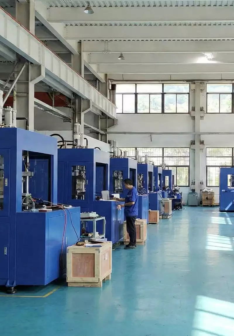
When translating the requirement into hardware, the HGY50-V3-EV machine configuration illustrates how injection, thermal conditioning, stretch-blow motion, and handling are organized on a compact one-step platform.
Questions that arise specifically in How to Plan Utilities for an ISBM Production Line
What utility is most often underestimated?
High-pressure blow air and cooling can be challenging because peak demand and distribution losses matter, not just average consumption.
Should I size a compressor from average air flow?
No. Consider simultaneous peak demand, pressure drop, storage and the required pressure at the machine during the blow event.
How do I size the resin dryer?
Use resin consumption per hour, required drying residence and hopper management for the specific resin.
Do I need separate low- and high-pressure air?
Many installations do because the process functions have different pressure requirements. Follow the machine connection design.
How much spare utility capacity should I leave?
Base it on a defined expansion scenario. Reserve enough for planned machines without operating the current system at inefficiently high pressure or oversized standby load.
Practical conclusion
For How to Plan Utilities for an ISBM Production Line, begin by documenting utility schedule, then test cooling water without moving unrelated settings, and release the process only after isolation and expansion is verified on every active cavity. Oversized high-pressure systems operated at unnecessary pressure can waste energy just as undersizing causes downtime.