
How Bottle Design Affects ISBM Mold Performance: Practical Technical Guide
For How Bottle Design Affects ISBM Mold Performance, the objective is not to find one universal setting. It is to prove which combination of height, shoulder transition, and neck finish produces the required bottle under stable factory conditions.
HeightEmbossingDesign for process margin
What this article must prove
Understand how bottle height, diameter, shoulder, base, ribs, panels, neck, wall target and asymmetry change mold pitch, stretch ratios, preform design, cooling, venting, cycle time and process margin. A defensible baseline begins with Greater body height generally increases axial stretch demand and rod travel. The first verification method is Compare stretchable preform length with final body length and machine stroke. From there, the article follows only checks that can materially change the answer promised by the title. Where an exact operating value depends on the resin grade, bottle drawing, mold, or delivered machine, the approved project specification controls the final setting.
✔️ Height
Greater body height generally increases axial stretch demand and rod travel. Compare stretchable preform length with final body length and machine stroke.
✔️ Body diameter
Larger diameter increases circumferential expansion and mold pitch. Calculate hoop ratio and check cavity spacing with cooling and clamp structure.
✔️ Shoulder transition
A steep shoulder changes surface area rapidly and can trap material near the neck or thin the upper panel. Use gradual geometry where branding allows and tune the preform/thermal profile to feed the shoulder.
The ASB-12 injection tooling replacement is a useful equipment example when the task involves mold exchange, dimensional matching, cooling performance, or repeatable transfer between ISBM stations.
Bottle Geometry Is a Process Input
Height
Height. Greater body height generally increases axial stretch demand and rod travel. Compare stretchable preform length with final body length and machine stroke. Link height to its consequence for stretch, pitch, cooling, venting, or handling before approving the bottle drawing. For this topic, the engineering log should connect height with the observed bottle condition and then test whether height supports the same diagnosis. A tall narrow bottle can starve the base if axial material transfer is not planned.
Height and Diameter Set Stretch Demand
Body diameter
Body diameter. Larger diameter increases circumferential expansion and mold pitch. Calculate hoop ratio and check cavity spacing with cooling and clamp structure. Link body diameter to its consequence for stretch, pitch, cooling, venting, or handling before approving the bottle drawing. Do not judge this factor from the HMI value alone; pair it with the actual bottle result, then continue with body diameter only after the relationship is clear. A diameter that barely fits can leave no room for robust mold cooling.
Shoulders Control Material Transfer
Shoulder transition
Shoulder transition. A steep shoulder changes surface area rapidly and can trap material near the neck or thin the upper panel. Use gradual geometry where branding allows and tune the preform/thermal profile to feed the shoulder. Link shoulder transition to its consequence for stretch, pitch, cooling, venting, or handling before approving the bottle drawing. Keep shoulder transition at its validated baseline while this item is tested so the bottle response can be attributed to one cause. Sharp transitions create a smaller process window.
Base mass
Base mass. Deep push-ups, feet and thick optical bases require material and cooling. Design the preform base and rod path to place resin before mold contact. Link base mass to its consequence for stretch, pitch, cooling, venting, or handling before approving the bottle drawing. Use the smallest controlled change that can prove the effect of base mass, then restore the baseline before a different adjustment such as base mass is tried. Trying to fill a deep base with pressure after the sidewall freezes produces thin or whitened zones.
Working terms for this specific task
- Height
- Greater body height generally increases axial stretch demand and rod travel.
- Body diameter
- Larger diameter increases circumferential expansion and mold pitch.
- Shoulder transition
- A steep shoulder changes surface area rapidly and can trap material near the neck or thin the upper panel.
- Base mass
- Deep push-ups, feet and thick optical bases require material and cooling.
Base Geometry Controls Heat and Stability
Ribs
Ribs. Ribs add surface area and need venting and sufficient local material temperature. Keep rib depth consistent with moldability and inspect wall thinning at rib roots. Link ribs to its consequence for stretch, pitch, cooling, venting, or handling before approving the bottle drawing. This factor belongs in the setup sheet because it directly changes the conditions under which ribs is evaluated. Deep ribs can create stress concentrations or incomplete definition.
| Item | Engineering question | Practical verification |
|---|---|---|
| Height | Greater body height generally increases axial stretch demand and rod travel. | Compare stretchable preform length with final body length and machine stroke. |
| Body diameter | Larger diameter increases circumferential expansion and mold pitch. | Calculate hoop ratio and check cavity spacing with cooling and clamp structure. |
| Shoulder transition | A steep shoulder changes surface area rapidly and can trap material near the neck or thin the upper panel. | Use gradual geometry where branding allows and tune the preform/thermal profile to feed the shoulder. |
| Base mass | Deep push-ups, feet and thick optical bases require material and cooling. | Design the preform base and rod path to place resin before mold contact. |
| Ribs | Ribs add surface area and need venting and sufficient local material temperature. | Keep rib depth consistent with moldability and inspect wall thinning at rib roots. |
| Embossing | Fine logos need mold contact and air escape without placing vent marks on critical appearance areas. | Coordinate engraving depth, polish and venting. |
| Release condition | Avoid combining maximum height, minimum wall, sharp shoulders, deep ribs and extreme base geometry without validation. Prototype or simulate difficult regions and keep tolerances tied to functional needs. | |
Ribs and Embossing Affect Mold Contact
Embossing
Embossing. Fine logos need mold contact and air escape without placing vent marks on critical appearance areas. Coordinate engraving depth, polish and venting. Link embossing to its consequence for stretch, pitch, cooling, venting, or handling before approving the bottle drawing. If the result differs by cavity, compare the local hardware related to embossing before moving on to embossing. Adding deeper engraving late can change wall stretch and release.
For this topic, the one-step ISBM machine portfolio provides useful equipment context for connecting the process requirement to an integrated resin-to-bottle platform.
Flat Panels Affect Cooling and Distortion
Flat panels
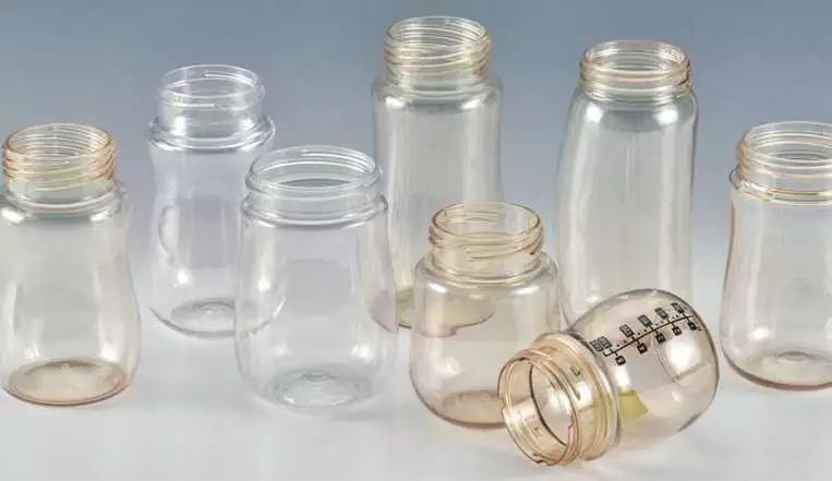
Flat panels. Large panels can oil-can or warp as residual heat and internal stress relax. Use ribs, curvature or controlled wall distribution and cooling where design permits. Link flat panels to its consequence for stretch, pitch, cooling, venting, or handling before approving the bottle drawing. This item is considered resolved only when the finding remains repeatable after thermal stabilization and the next check, flat panels, does not contradict it. A perfectly flat CAD surface may be less stable than a subtly curved panel.
Oval shape
Oval shape. Major and minor axes require different radial draw. Plan preform orientation and preferential thermal control. Link oval shape to its consequence for stretch, pitch, cooling, venting, or handling before approving the bottle drawing. For repeatability, define who measures oval shape, where it is measured, and what bottle evidence is required before checking oval shape. Uniform heating often creates a thin long-axis wall.
Neck Finish Controls Pitch and Heat Protection
Neck finish
Neck finish. Large necks consume cavity pitch and must be protected from blow-stage heat. Check lip-cavity cooling, closure dimensions and mold layout. Link neck finish to its consequence for stretch, pitch, cooling, venting, or handling before approving the bottle drawing. Record the bottle response beside the setting or measurement for neck finish; that record becomes the starting condition when neck finish is reviewed. A wide-mouth design can reduce cavitation enough to change machine economics.
Design for a Wide Process Window, Not Just Appearance
Design for process margin
Design for process margin. Avoid combining maximum height, minimum wall, sharp shoulders, deep ribs and extreme base geometry without validation. Prototype or simulate difficult regions and keep tolerances tied to functional needs. Link design for process margin to its consequence for stretch, pitch, cooling, venting, or handling before approving the bottle drawing. If the symptom or performance target does not move as predicted, return design for process margin to the baseline and investigate design for process margin rather than stacking corrections. A bottle can be technically moldable but too sensitive for stable mass production.
Neck finish: release evidence
Large necks consume cavity pitch and must be protected from blow-stage heat. Check lip-cavity cooling, closure dimensions and mold layout. The condition is accepted only when the relevant bottle measurement or functional test remains stable after the process reaches normal operating temperature.
Design for process margin: failure boundary
A bottle can be technically moldable but too sensitive for stable mass production. Use that failure mode as the boundary for the trial and return to the previous stable condition when the bottle response moves in the wrong direction.
When translating the requirement into hardware, the HGY50-V3-EV machine configuration illustrates how injection, thermal conditioning, stretch-blow motion, and handling are organized on a compact one-step platform.
Questions that arise specifically in How Bottle Design Affects ISBM Mold Performance
Which bottle feature most affects mold performance?
There is no single feature. Stretch demand, neck pitch, base heat load, asymmetry and decoration can each become limiting.
Why do sharp shoulders cause wall problems?
They require rapid changes in material direction and surface area, making thermal and stretch timing more sensitive.
Can mold cooling fix an unstable flat panel?
Cooling helps, but panel geometry, wall distribution and residual stress may also need redesign.
Why does a larger neck reduce cavities?
The lip/neck tooling needs physical pitch and cooling space, which can set the mold spacing before the bottle body does.
How do I make a bottle easier to mold?
Use smoother transitions, adequate wall budget, realistic stretch ratios, ventable details, stable base geometry and tolerances based on function rather than appearance alone.
Practical conclusion
The final decision on How Bottle Design Affects ISBM Mold Performance is made by the bottle, not by a single displayed parameter. Use height to establish the input, embossing to test the mechanism, and design for process margin to prove the output under stable conditions. A bottle can be technically moldable but too sensitive for stable mass production.