
How Does One-Step ISBM Molding Work?: Practical Technical Guide
This guide treats How Does One-Step ISBM Molding Work? as a sequence of measurable decisions. It begins with the physical product requirement, then tests the process mechanisms that can change the bottle, and finishes with a release condition that can be documented.
Resin preparationPre-blow and final blowQuality feedback
이 기사가 입증해야 할 것
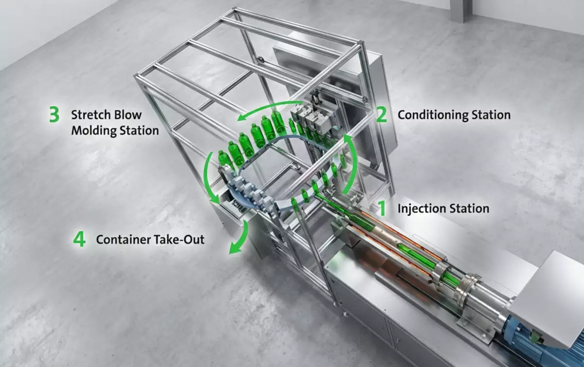
Understand the complete one-step isbm sequence from dry resin to finished bottle and how injection, conditioning, axial stretching, radial blowing, cooling and ejection interact. A defensible baseline begins with Hygroscopic resins such as PET require controlled drying before plasticizing; other materials have their own preparation requirements. The first verification method is Feed the machine only after the resin handling system reaches the condition specified for the selected grade and keep the conveying path protected from moisture pickup. From there, the article follows only checks that can materially change the answer promised by the title. Where an exact operating value depends on the resin grade, bottle drawing, mold, or delivered machine, the approved project specification controls the final setting.
✔️ Resin preparation
Hygroscopic resins such as PET require controlled drying before plasticizing; other materials have their own preparation requirements. Feed the machine only after the resin handling system reaches the condition specified for the selected grade and keep the conveying path protected from moisture pickup.
✔️ Injection molding
The injection unit melts and meters resin into the preform cavity, forming the neck finish and a thick tubular body intended for later stretching. Control fill, pack, cooling and shot consistency so every preform leaves injection with stable mass, neck dimensions and thermal history.
✔️ Neck retention
One-step machines typically keep the molded neck or lip region located in a neck-holding component while the body passes through later stations. Protect the neck from unnecessary heat and mechanical distortion because closure fit depends on the injection-molded geometry.
그만큼 ASB 호환 툴링 구성 금형 교체, 문제 해결 또는 생산 능력 변경 시 금형 인터페이스와 기계 동작이 어떻게 호환되어야 하는지 확인할 때도 이 점이 중요합니다.
From Resin Pellet to Preform
Resin preparation
Resin preparation. Hygroscopic resins such as PET require controlled drying before plasticizing; other materials have their own preparation requirements. Feed the machine only after the resin handling system reaches the condition specified for the selected grade and keep the conveying path protected from moisture pickup. Use measurable bottle and machine evidence to verify resin preparation before accepting the conclusion. Use this result to narrow the process window, not to create a new universal setpoint; the next constraint to confirm is resin preparation. Wet resin or unstable material feed can change melt quality before molding adjustments even begin.
Why the Neck Is Finished During Injection
Injection molding
Injection molding. The injection unit melts and meters resin into the preform cavity, forming the neck finish and a thick tubular body intended for later stretching. Control fill, pack, cooling and shot consistency so every preform leaves injection with stable mass, neck dimensions and thermal history. Use measurable bottle and machine evidence to verify injection molding before accepting the conclusion. The expected response should be visible in a bottle measurement, defect map, or machine trend before the team proceeds to injection molding. A preform variation becomes a bottle variation because the blow stage can redistribute material but cannot create missing resin.
Neck retention
Neck retention. One-step machines typically keep the molded neck or lip region located in a neck-holding component while the body passes through later stations. Protect the neck from unnecessary heat and mechanical distortion because closure fit depends on the injection-molded geometry. Use measurable bottle and machine evidence to verify neck retention before accepting the conclusion. Once this check is stable, the next useful question is whether neck retention changes the same bottle region or affects a different part of the process. If the neck softens or is mislocated, cap torque and sealing problems can appear even when the body is visually acceptable.
How the Preform Is Conditioned Before Blowing
Thermal conditioning
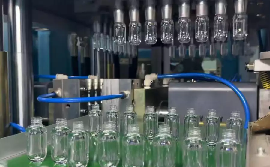
Thermal conditioning. Between injection and stretch blowing, the preform temperature is allowed or actively forced to a profile suitable for orientation. Use available core, cavity, conditioning, cooling or heating controls to create the temperature distribution needed by shoulder, panel and base geometry. Use measurable bottle and machine evidence to verify thermal conditioning before accepting the conclusion. This checkpoint should be evaluated before thermal conditioning is altered, because otherwise two process mechanisms change at the same time. Uniform surface temperature does not always mean uniform through-wall temperature, so tuning only one measurement can be misleading.
본 특정 업무에 대한 근로 조건
- Resin preparation
- Hygroscopic resins such as PET require controlled drying before plasticizing; other materials have their own preparation requirements.
- Injection molding
- The injection unit melts and meters resin into the preform cavity, forming the neck finish and a thick tubular body intended for later stretching.
- Neck retention
- One-step machines typically keep the molded neck or lip region located in a neck-holding component while the body passes through later stations.
- Thermal conditioning
- Between injection and stretch blowing, the preform temperature is allowed or actively forced to a profile suitable for orientation.
What the Stretch Rod Does
Axial stretching
Axial stretching. The stretch rod moves through the preform and mechanically draws material toward the base before or during radial expansion. Set rod start, speed and end position so the preform develops controlled axial draw before the bottle wall locks against the mold. Use measurable bottle and machine evidence to verify axial stretching before accepting the conclusion. For this topic, the engineering log should connect axial stretching with the observed bottle condition and then test whether axial stretching supports the same diagnosis. If radial blowing dominates too early, material can remain heavy near the shoulder and thin near the base or panel.
Pre-blow and final blow
Pre-blow and final blow. Air expands the stretched preform radially until it contacts the cooled blow mold; some processes use staged pressure or timing. Adjust timing and pressure only within the machine and bottle process window and watch how each change shifts material and detail reproduction. Use measurable bottle and machine evidence to verify pre-blow and final blow before accepting the conclusion. Do not judge this factor from the HMI value alone; pair it with the actual bottle result, then continue with pre-blow and final blow only after the relationship is clear. More pressure cannot compensate for a cold or badly designed preform and may increase utility cost or mechanical stress.
공구 관련 결정을 내릴 때, ASB-12 대체 금형 설계 치수 인터페이스, 냉각 연결, 캐비티 형상 및 전송 정렬이 장비 설정의 일부로 고려되어야 하는 이유를 강조합니다.
| 목 | 공학적 질문 | 실질적인 검증 |
|---|---|---|
| Resin preparation | Hygroscopic resins such as PET require controlled drying before plasticizing; other materials have their own preparation requirements. | Feed the machine only after the resin handling system reaches the condition specified for the selected grade and keep the conveying path protected from moisture pickup. |
| Injection molding | The injection unit melts and meters resin into the preform cavity, forming the neck finish and a thick tubular body intended for later stretching. | Control fill, pack, cooling and shot consistency so every preform leaves injection with stable mass, neck dimensions and thermal history. |
| Neck retention | One-step machines typically keep the molded neck or lip region located in a neck-holding component while the body passes through later stations. | Protect the neck from unnecessary heat and mechanical distortion because closure fit depends on the injection-molded geometry. |
| Thermal conditioning | Between injection and stretch blowing, the preform temperature is allowed or actively forced to a profile suitable for orientation. | Use available core, cavity, conditioning, cooling or heating controls to create the temperature distribution needed by shoulder, panel and base geometry. |
| Axial stretching | The stretch rod moves through the preform and mechanically draws material toward the base before or during radial expansion. | Set rod start, speed and end position so the preform develops controlled axial draw before the bottle wall locks against the mold. |
| Pre-blow and final blow | Air expands the stretched preform radially until it contacts the cooled blow mold; some processes use staged pressure or timing. | Adjust timing and pressure only within the machine and bottle process window and watch how each change shifts material and detail reproduction. |
| 릴리스 조건 | Bottle weight, wall distribution, dimensions, visual appearance and functional tests provide feedback to the earlier process stages. Trace each defect backward to the preform, thermal profile, stretch timing, blow event, cooling or handling mechanism most capable of creating it. | |
How Blow Air Expands the Preform
Mold contact
Mold contact. Once the polymer contacts the cavity surface, heat transfers into the mold and the bottle takes the engraved surface, split-line and base geometry. Keep mold cooling balanced and venting clear so air can escape as polymer reaches corners and fine details. Use measurable bottle and machine evidence to verify mold contact before accepting the conclusion. Keep mold contact at its validated baseline while this item is tested so the bottle response can be attributed to one cause. Trapped air, hot mold zones or blocked vents can cause poor definition, haze, sticking or dimensional drift.
How Cooling Freezes the Final Shape
Ejection
Ejection. The molded container is released from the neck holder or take-out mechanism and transferred to downstream handling. Check that the bottle has enough rigidity for removal and that conveyors do not squeeze a still-warm base or shoulder. Use measurable bottle and machine evidence to verify ejection before accepting the conclusion. Use the smallest controlled change that can prove the effect of ejection, then restore the baseline before a different adjustment such as ejection is tried. A bottle can be molded correctly and then deform in the first seconds after ejection.
Cycle synchronization
Cycle synchronization. Injection, conditioning, blowing and ejection occur as a coordinated indexed cycle, so the slowest stable station limits output. Trend actual station times and change one variable at a time when reducing cycle. Use measurable bottle and machine evidence to verify cycle synchronization before accepting the conclusion. This factor belongs in the setup sheet because it directly changes the conditions under which cycle synchronization is evaluated. Optimizing one station in isolation can simply move the bottleneck or create a defect in the next station.
Why All Stations Must Be Balanced as One Cycle
Quality feedback
Quality feedback. Bottle weight, wall distribution, dimensions, visual appearance and functional tests provide feedback to the earlier process stages. Trace each defect backward to the preform, thermal profile, stretch timing, blow event, cooling or handling mechanism most capable of creating it. Use measurable bottle and machine evidence to verify quality feedback before accepting the conclusion. If the result differs by cavity, compare the local hardware related to quality feedback before moving on to quality feedback. Random parameter changes hide cause and effect and make the process less repeatable.
Cycle synchronization: release evidence
Injection, conditioning, blowing and ejection occur as a coordinated indexed cycle, so the slowest stable station limits output. Trend actual station times and change one variable at a time when reducing cycle. The condition is accepted only when the relevant bottle measurement or functional test remains stable after the process reaches normal operating temperature.
Quality feedback: failure boundary
Random parameter changes hide cause and effect and make the process less repeatable. Use that failure mode as the boundary for the trial and return to the previous stable condition when the bottle response moves in the wrong direction.
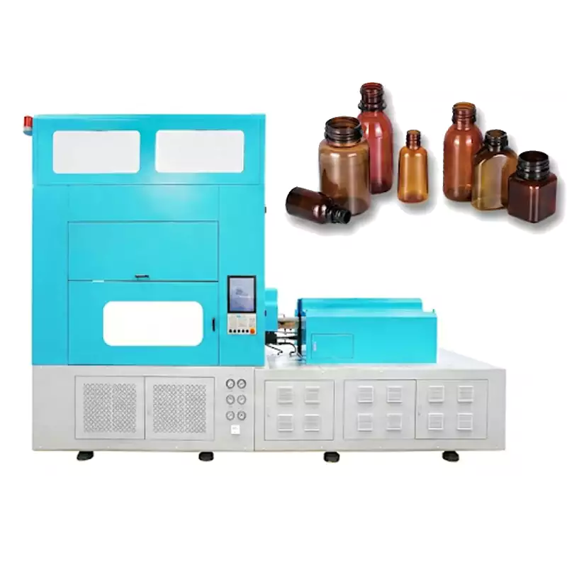
요구사항을 하드웨어로 변환할 때, HGY50-V3-EV 기계 구성 사출, 열처리, 스트레치 블로우 동작 및 핸들링이 어떻게 컴팩트한 원스텝 플랫폼에 구성되는지 보여줍니다.
Questions that arise specifically in How Does One-Step ISBM Molding Work?
What makes one-step ISBM different from injection blow molding?
ISBM adds deliberate axial stretching plus radial blowing, creating biaxial orientation in the stretchable body where the resin and process allow it.
Why is the neck molded before the bottle body?
The closure finish requires injection-molded dimensional precision. The body remains as a thicker preform so it can be stretched later.
Does the preform cool completely before blowing?
In one-step processing it normally remains within an integrated thermal path rather than being stored cold and reheated as in a conventional two-step route.
Which station controls wall thickness most?
No single station acts alone. Preform geometry, thermal conditioning, stretch timing, blow timing and mold contact jointly determine material distribution.
Why does cycle balance matter?
The indexed process advances only when the synchronized stations are ready, so the slowest stable stage determines overall cycle time.
실질적인 결론
For How Does One-Step ISBM Molding Work?, begin by documenting resin preparation, then test pre-blow and final blow without moving unrelated settings, and release the process only after quality feedback is verified on every active cavity. Random parameter changes hide cause and effect and make the process less repeatable.