
How to Plan an ISBM Machine Factory Layout: Practical Technical Guide
How to Plan an ISBM Machine Factory Layout is a practical engineering question, so this guide starts with resin flow, moves through machine access, and ends with bottle-level verification rather than generic ISBM background.
Resin flowBottle flowExpansion
What this article must prove
Plan an isbm factory layout that supports resin flow, molds, utilities, operator access, maintenance lifting, finished-bottle handling, quality inspection, safety and future expansion. A defensible baseline begins with Place silos, dryers, day bins and conveying routes to minimize unnecessary transfer length and contamination points. The first verification method is Keep material identity and color-change paths clear. From there, the article follows only checks that can materially change the answer promised by the title. Where an exact operating value depends on the resin grade, bottle drawing, mold, or delivered machine, the approved project specification controls the final setting.
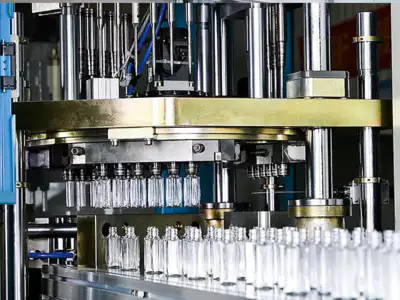
✔️ Resin flow
Place silos, dryers, day bins and conveying routes to minimize unnecessary transfer length and contamination points. Keep material identity and color-change paths clear.
✔️ Machine access
Use the supplier service envelope, door swing, electrical cabinet and mold-access requirements. Mark maintenance clearance on the floor plan rather than drawing only machine footprint.
✔️ Mold handling
Plan crane, hoist or forklift approach and safe staging for injection and blow tooling. Check load rating, lift height and turning radius.
그만큼 ASB-compatible tooling configuration is also relevant when checking how mold interfaces and machine motion must remain compatible during replacement, troubleshooting, or capacity changes.
Draw Material Flow Before Placing Machines
Resin flow
Resin flow. Place silos, dryers, day bins and conveying routes to minimize unnecessary transfer length and contamination points. Keep material identity and color-change paths clear. Put resin flow on the scaled factory drawing with service clearance and real traffic paths instead of relying on the machine footprint. Once this check is stable, the next useful question is whether resin flow changes the same bottle region or affects a different part of the process. Long complicated routing increases pressure loss, cleaning time and mix-up risk.
Set Machine Orientation around Mold Changes and Service
Machine access
Machine access. Use the supplier service envelope, door swing, electrical cabinet and mold-access requirements. Mark maintenance clearance on the floor plan rather than drawing only machine footprint. Put machine access on the scaled factory drawing with service clearance and real traffic paths instead of relying on the machine footprint. This checkpoint should be evaluated before machine access is altered, because otherwise two process mechanisms change at the same time. A compact layout that blocks a pump, screw pull or mold plate can make future service extremely expensive.
Create a Safe Mold-Handling Route
Mold handling
Mold handling. Plan crane, hoist or forklift approach and safe staging for injection and blow tooling. Check load rating, lift height and turning radius. Put mold handling on the scaled factory drawing with service clearance and real traffic paths instead of relying on the machine footprint. For this topic, the engineering log should connect mold handling with the observed bottle condition and then test whether mold handling supports the same diagnosis. Moving heavy tooling through operator aisles increases safety and damage risk.
Air header
Air header. Keep high-pressure piping short, adequately sized and arranged to avoid unnecessary elbows and dead legs. Place receivers or local storage where engineering analysis requires them. Put air header on the scaled factory drawing with service clearance and real traffic paths instead of relying on the machine footprint. Do not judge this factor from the HMI value alone; pair it with the actual bottle result, then continue with air header only after the relationship is clear. A distant small header can create blow-pulse pressure drop.
Working terms for this specific task
- Resin flow
- Place silos, dryers, day bins and conveying routes to minimize unnecessary transfer length and contamination points.
- Machine access
- Use the supplier service envelope, door swing, electrical cabinet and mold-access requirements.
- Mold handling
- Plan crane, hoist or forklift approach and safe staging for injection and blow tooling.
- Air header
- Keep high-pressure piping short, adequately sized and arranged to avoid unnecessary elbows and dead legs.
Route Utilities for Low Pressure Drop and Easy Isolation
Water manifolds
Water manifolds. Provide accessible supply/return manifolds, flow indication and drain points. Avoid hoses across walkways and provide isolation per machine. Put water manifolds on the scaled factory drawing with service clearance and real traffic paths instead of relying on the machine footprint. Keep water manifolds at its validated baseline while this item is tested so the bottle response can be attributed to one cause. Poor routing encourages kinked hoses and makes leak repair disruptive.
| 목 | Engineering question | Practical verification |
|---|---|---|
| Resin flow | Place silos, dryers, day bins and conveying routes to minimize unnecessary transfer length and contamination points. | Keep material identity and color-change paths clear. |
| Machine access | Use the supplier service envelope, door swing, electrical cabinet and mold-access requirements. | Mark maintenance clearance on the floor plan rather than drawing only machine footprint. |
| Mold handling | Plan crane, hoist or forklift approach and safe staging for injection and blow tooling. | Check load rating, lift height and turning radius. |
| Air header | Keep high-pressure piping short, adequately sized and arranged to avoid unnecessary elbows and dead legs. | Place receivers or local storage where engineering analysis requires them. |
| Water manifolds | Provide accessible supply/return manifolds, flow indication and drain points. | Avoid hoses across walkways and provide isolation per machine. |
| Bottle flow | Take bottles away without long drops, tight guides or accumulation that can deform warm parts. | Coordinate conveyor height and orientation with inspection, filling or packing. |
| Release condition | Reserve machine bays, utility branches and conveyor routes for the likely next phase. Keep future equipment from blocking current maintenance routes. | |
Design Bottle Take-Out and Downstream Flow
Bottle flow
Bottle flow. Take bottles away without long drops, tight guides or accumulation that can deform warm parts. Coordinate conveyor height and orientation with inspection, filling or packing. Put bottle flow on the scaled factory drawing with service clearance and real traffic paths instead of relying on the machine footprint. Use the smallest controlled change that can prove the effect of bottle flow, then restore the baseline before a different adjustment such as bottle flow is tried. A good molding process can lose yield immediately after ejection.
For this topic, the one-step ISBM machine portfolio provides useful equipment context for connecting the process requirement to an integrated resin-to-bottle platform.
Place Quality and Scrap Handling Near the Process
Quality station
Quality station. Provide controlled lighting, gauges and sample storage close enough for rapid checks without obstructing production. Design cavity sample collection and quarantine areas. Put quality station on the scaled factory drawing with service clearance and real traffic paths instead of relying on the machine footprint. This factor belongs in the setup sheet because it directly changes the conditions under which quality station is evaluated. If inspection is inconvenient, checks tend to be delayed or inconsistent.
Scrap flow
Scrap flow. Separate clean resin and good bottles from reject grinding, dust and maintenance debris. Use closed scrap handling where required. Put scrap flow on the scaled factory drawing with service clearance and real traffic paths instead of relying on the machine footprint. If the result differs by cavity, compare the local hardware related to scrap flow before moving on to scrap flow. Open scrap bins beside clear-bottle production can become a contamination source.
Separate Clean Product Flow from Maintenance Traffic
People and safety
People and safety. Maintain clear egress, guard-door access, electrical clearances and safe interaction with forklifts. Review layout with operators, maintenance and safety teams before installation. Put people and safety on the scaled factory drawing with service clearance and real traffic paths instead of relying on the machine footprint. This item is considered resolved only when the finding remains repeatable after thermal stabilization and the next check, people and safety, does not contradict it. A technically efficient layout can still be unsafe or difficult to operate.
Reserve Expansion Space and Utility Corridors
Expansion
Expansion. Reserve machine bays, utility branches and conveyor routes for the likely next phase. Keep future equipment from blocking current maintenance routes. Put expansion on the scaled factory drawing with service clearance and real traffic paths instead of relying on the machine footprint. For repeatability, define who measures expansion, where it is measured, and what bottle evidence is required before checking expansion. Unplanned expansion often creates the worst pressure drops and most congested service access in a plant.
People and safety: release evidence
Maintain clear egress, guard-door access, electrical clearances and safe interaction with forklifts. Review layout with operators, maintenance and safety teams before installation. The condition is accepted only when the relevant bottle measurement or functional test remains stable after the process reaches normal operating temperature.
Expansion: failure boundary
Unplanned expansion often creates the worst pressure drops and most congested service access in a plant. Use that failure mode as the boundary for the trial and return to the previous stable condition when the bottle response moves in the wrong direction.
그만큼 multi-material ISBM platform overview also helps frame how machine architecture, materials, utilities, and bottle applications fit together at line level.
Questions that arise specifically in How to Plan an ISBM Machine Factory Layout
How much space should I leave around an ISBM machine?
Use the delivered machine service and safety envelope, including mold handling, cabinet access and component-removal paths, not a generic clearance.
Where should the dryer be located?
Close enough for efficient resin handling while maintaining service, heat rejection and clean material flow. Follow equipment requirements.
Why plan mold handling early?
Injection and blow molds are heavy and precision components; safe lifting and staging can determine machine orientation.
Should the compressor be beside the machine?
Not necessarily. Central or local systems can work, but high-pressure distribution must meet dynamic flow and pressure requirements.
What is the most common expansion mistake?
Adding machines to an existing air or cooling branch without recalculating simultaneous load and maintenance access.
Practical conclusion
The working method for How to Plan an ISBM Machine Factory Layout is evidence first: establish resin flow, isolate the effect of bottle flow, and use expansion as the final production check. Long complicated routing increases pressure loss, cleaning time and mix-up risk.