
How to Diagnose High-Pressure Air Leaks in ISBM: Practical Technical Guide
How to Diagnose High-Pressure Air Leaks in ISBM is a practical engineering question, so this guide starts with symptom definition, moves through dynamic pressure, and ends with bottle-level verification rather than generic ISBM background.
Symptom definitionBlow valvesPost-repair proof
Apa yang mesti dibuktikan oleh artikel ini
Locate high-pressure air leaks and pressure losses by dividing the system into compressor/booster, receiver, header, machine inlet, valve manifold, cavity seals and exhaust path. A defensible baseline begins with A leak wastes air continuously or during a valve event, while a restriction creates pressure drop when flow rises. The first verification method is Record supply and machine pressure through the full cycle. From there, the article follows only checks that can materially change the answer promised by the title. Where an exact operating value depends on the resin grade, bottle drawing, mold, or delivered machine, the approved project specification controls the final setting.
✔️ Symptom definition
A leak wastes air continuously or during a valve event, while a restriction creates pressure drop when flow rises. Record supply and machine pressure through the full cycle.
✔️ Dynamic pressure
Measure near the machine because blow demand is short and high-flow. Use a sensor with enough response to capture the pressure dip during blowing.
✔️ Plant header
Compare pressure upstream and downstream of long piping, filters, dryers or boosters. Test under normal simultaneous demand from other machines.
Yang ISBM replacement mold design reinforces the practical need to control mounting geometry, thermal behavior, transfer position, and cavity alignment rather than treating the mold as an isolated component.
First Decide: Leak or Pressure Drop?
Symptom definition
Symptom definition. A leak wastes air continuously or during a valve event, while a restriction creates pressure drop when flow rises. Record supply and machine pressure through the full cycle. The diagnostic test should show whether symptom definition can physically create the observed defect before a repair or parameter change is accepted. Record the bottle response beside the setting or measurement for symptom definition; that record becomes the starting condition when symptom definition is reviewed. Replacing seals will not fix an undersized or restricted header.
Measure Pressure at the Machine during the Blow Pulse
Dynamic pressure
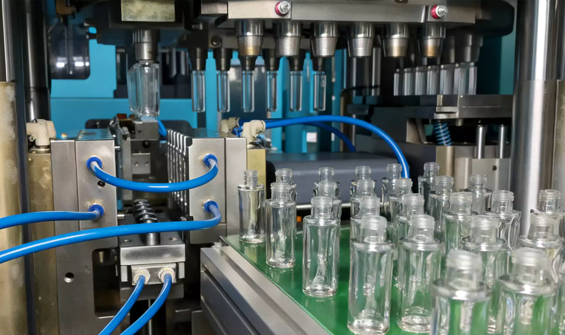
Dynamic pressure. Measure near the machine because blow demand is short and high-flow. Use a sensor with enough response to capture the pressure dip during blowing. The diagnostic test should show whether dynamic pressure can physically create the observed defect before a repair or parameter change is accepted. If the symptom or performance target does not move as predicted, return dynamic pressure to the baseline and investigate dynamic pressure rather than stacking corrections. A compressor-room gauge can remain steady while local machine pressure collapses.
Isolate the Plant Header from the Machine
Plant header
Plant header. Compare pressure upstream and downstream of long piping, filters, dryers or boosters. Test under normal simultaneous demand from other machines. The diagnostic test should show whether plant header can physically create the observed defect before a repair or parameter change is accepted. If a change improves one region but worsens another, compare the material or energy movement between plant header and plant header instead of accepting the first visual improvement. A system that works during a single-machine trial can fail when the factory is fully loaded.
Receiver and storage
Receiver and storage. Check whether local air storage and control strategy can support the pulse without excessive pressure swing. Compare pressure recovery between cycles. The diagnostic test should show whether receiver and storage can physically create the observed defect before a repair or parameter change is accepted. Where the outcome depends on material grade or tooling geometry, confirm the approved project limit and then use receiver and storage as the next cross-check. Insufficient storage can force the compressor setpoint higher than the process actually needs.
Terma kerja untuk tugasan khusus ini
- Symptom definition
- A leak wastes air continuously or during a valve event, while a restriction creates pressure drop when flow rises.
- Dynamic pressure
- Measure near the machine because blow demand is short and high-flow.
- Plant header
- Compare pressure upstream and downstream of long piping, filters, dryers or boosters.
- Receiver and storage
- Check whether local air storage and control strategy can support the pulse without excessive pressure swing.
Check Hoses, Fittings and Manifolds
Fittings and hoses
Fittings and hoses. Inspect joints, flexible hoses and quick connections for damage, looseness and undersizing. Use approved leak detection during a safe maintenance state. The diagnostic test should show whether fittings and hoses can physically create the observed defect before a repair or parameter change is accepted. When the project is near a machine or material limit, require a molding trial that isolates fittings and hoses and then challenges fittings and hoses under the same bottle specification. A small leak at high pressure can waste substantial energy and may be hazardous.
| Barang | Soalan kejuruteraan | Pengesahan praktikal |
|---|---|---|
| Symptom definition | A leak wastes air continuously or during a valve event, while a restriction creates pressure drop when flow rises. | Record supply and machine pressure through the full cycle. |
| Dynamic pressure | Measure near the machine because blow demand is short and high-flow. | Use a sensor with enough response to capture the pressure dip during blowing. |
| Plant header | Compare pressure upstream and downstream of long piping, filters, dryers or boosters. | Test under normal simultaneous demand from other machines. |
| Receiver and storage | Check whether local air storage and control strategy can support the pulse without excessive pressure swing. | Compare pressure recovery between cycles. |
| Fittings and hoses | Inspect joints, flexible hoses and quick connections for damage, looseness and undersizing. | Use approved leak detection during a safe maintenance state. |
| Blow valves | A valve may leak past its seat, open slowly or fail to deliver expected flow. | Compare cavity behavior and pressure traces and service valves using the machine procedure. |
| Keadaan pelepasan | Repeat the same dynamic pressure and production test after repair. Confirm bottle quality, air consumption and pressure stability improve without increasing setpoint. | |
Check Blow Valves and Cavity Seals
Blow valves
Blow valves. A valve may leak past its seat, open slowly or fail to deliver expected flow. Compare cavity behavior and pressure traces and service valves using the machine procedure. The diagnostic test should show whether blow valves can physically create the observed defect before a repair or parameter change is accepted. The safest interpretation comes from comparing at least several stable cycles and then verifying blow valves without changing the rest of the recipe. Raising supply pressure to compensate increases demand for every cavity.
Bagi keputusan berkaitan perkakasan, Kejuruteraan acuan penggantian ASB-12 mengetengahkan mengapa antara muka dimensi, sambungan penyejukan, geometri rongga dan penjajaran pemindahan mesti dianggap sebagai sebahagian daripada persediaan mesin.
Use Downtime Leak Testing Safely
Cavity seals
Cavity seals. Inspect neck seals, blow-core seals and moving interfaces for wear or misalignment. Look for a cavity-specific hiss or under-blow pattern during controlled testing. The diagnostic test should show whether cavity seals can physically create the observed defect before a repair or parameter change is accepted. A useful production trial keeps the resin lot and cavity identification fixed while cavity seals is changed, followed by a separate check of cavity seals. A worn seal can produce both air waste and bottle quality variation.
Exhaust circuit
Exhaust circuit. Check whether valves exhaust at the intended point and whether recovery or recycling circuits operate correctly where fitted. Review sequence timing and muffler/recovery condition. The diagnostic test should show whether exhaust circuit can physically create the observed defect before a repair or parameter change is accepted. The practical value of this check is that it turns exhaust circuit from a vague setting into evidence that can be compared with exhaust circuit. A stuck exhaust or recovery valve can alter both cycle and air use.
Quantify the Cost and Production Impact
Leak quantification
Leak quantification. Estimate leakage from measured compressor flow, pressure decay or plant-approved audit method. Convert the verified leak rate into annual energy and maintenance priority. The diagnostic test should show whether leak quantification can physically create the observed defect before a repair or parameter change is accepted. Use this result to narrow the process window, not to create a new universal setpoint; the next constraint to confirm is leak quantification. Unmeasured leak programs tend to fix obvious noises while missing the largest loss.
Verify Repair with the Same Pressure Trace
Post-repair proof
Post-repair proof. Repeat the same dynamic pressure and production test after repair. Confirm bottle quality, air consumption and pressure stability improve without increasing setpoint. The diagnostic test should show whether post-repair proof can physically create the observed defect before a repair or parameter change is accepted. The expected response should be visible in a bottle measurement, defect map, or machine trend before the team proceeds to post-repair proof. A quieter machine is not proof that the high-flow pressure problem is solved.
Leak quantification: release evidence
Estimate leakage from measured compressor flow, pressure decay or plant-approved audit method. Convert the verified leak rate into annual energy and maintenance priority. The condition is accepted only when the relevant bottle measurement or functional test remains stable after the process reaches normal operating temperature.
Post-repair proof: failure boundary
A quieter machine is not proof that the high-flow pressure problem is solved. Use that failure mode as the boundary for the trial and return to the previous stable condition when the bottle response moves in the wrong direction.
Untuk topik ini, portfolio mesin ISBM satu langkah menyediakan konteks peralatan yang berguna untuk menghubungkan keperluan proses ke platform resin-ke-botol bersepadu.
Questions that arise specifically in How to Diagnose High-Pressure Air Leaks in ISBM
Why does pressure look normal until the machine blows?
The restriction or storage problem only appears when instantaneous flow rises during the blow event.
Is a hissing sound always a serious leak?
It indicates leakage that should be assessed safely, but quantify location and rate before prioritizing repairs.
Should I raise compressor pressure when bottles under-blow?
Not before checking local pressure drop, valves, seals, venting, thermal conditions and the actual process requirement.
How do I compare cavities?
Track bottle defect and local valve/seal condition by cavity; a cavity-specific issue is unlikely to be caused by the central compressor alone.
What proves a successful repair?
Lower verified leakage or pressure drop plus stable blow pressure and bottle quality under normal factory demand.
Kesimpulan praktikal
The working method for How to Diagnose High-Pressure Air Leaks in ISBM is evidence first: establish symptom definition, isolate the effect of blow valves, and use post-repair proof as the final production check. Replacing seals will not fix an undersized or restricted header.