
आईएसबीएम में बोतल की दीवार की मोटाई को कैसे नियंत्रित करें: व्यावहारिक तकनीकी मार्गदर्शिका
आईएसबीएम में बोतल की दीवार की मोटाई को कैसे नियंत्रित किया जाए, इस प्रश्न का उपयोगी उत्तर मोटाई मानचित्र, रॉड गति प्रोफ़ाइल और गुहा सत्यापन के बीच परस्पर क्रिया से प्राप्त होता है। नीचे दिए गए अनुभाग इन कारकों को ऐसे जाँचों में परिवर्तित करते हैं जिन्हें उत्पादन मशीन पर दोहराया जा सकता है।
मोटाई मानचित्ररॉड गति प्रोफ़ाइलगुहा सत्यापन
इस लेख को क्या साबित करना होगा
प्रीफॉर्म की ज्यामिति, थर्मल प्रोफाइल, स्ट्रेच-रॉड की गति, एयर टाइमिंग और मोल्ड कूलिंग को नियंत्रित करके बोतल की अंतिम दीवार की मोटाई को नियंत्रित करें, फिर एक दोहराने योग्य मोटाई मानचित्र के साथ परिणाम को सत्यापित करें। एक विश्वसनीय आधार रेखा कंधे, ऊपरी साइडवॉल, मध्य भाग, निचले पैनल, एड़ी और आधार पर माप बैंड परिभाषित करके शुरू होती है, जिसमें प्रत्येक बैंड पर कई परिधीय बिंदु होते हैं। पहली सत्यापन विधि प्रत्येक परीक्षण के लिए समान कट स्थानों और उपकरण विधि का उपयोग करना है। इसके बाद, लेख केवल उन जाँचों का अनुसरण करता है जो शीर्षक द्वारा दिए गए उत्तर को महत्वपूर्ण रूप से बदल सकती हैं। जहाँ एक सटीक परिचालन मान राल ग्रेड, बोतल ड्राइंग, मोल्ड या वितरित मशीन पर निर्भर करता है, वहाँ अनुमोदित परियोजना विनिर्देश अंतिम सेटिंग को नियंत्रित करता है।
✔️ मोटाई का नक्शा
कंधे, ऊपरी पार्श्व भाग, मध्य भाग, निचले पैनल, एड़ी और आधार पर माप बैंड निर्धारित करें, और प्रत्येक बैंड पर कई परिधीय बिंदु बनाएं। प्रत्येक परीक्षण के लिए समान कट स्थान और उपकरण विधि का उपयोग करें।
✔️ प्रीफॉर्म द्रव्यमान वितरण
प्रीफॉर्म की दीवार की मोटाई और टेपर यह निर्धारित करते हैं कि बोतल के प्रत्येक भाग के लिए कितनी सामग्री उपलब्ध है। मशीन को ट्यून करने से पहले प्रीफॉर्म प्रोफाइल की तुलना बोतल के सतह क्षेत्र और जटिल विशेषताओं से करें।
✔️ अक्षीय तापीय प्रोफ़ाइल
रेज़िन प्रक्रिया के दौरान, गर्म क्षेत्र आमतौर पर अधिक आसानी से फैलते हैं जबकि ठंडे क्षेत्र फैलने का प्रतिरोध करते हैं। छोटे-छोटे क्षेत्रों में कंडीशनिंग को समायोजित करें और अगली मोटाई के मानचित्र की तुलना करें।
The ASB-संगत टूलिंग कॉन्फ़िगरेशन यह तब भी प्रासंगिक होता है जब यह जांच की जाती है कि प्रतिस्थापन, समस्या निवारण या क्षमता परिवर्तन के दौरान मोल्ड इंटरफेस और मशीन की गति संगत बनी रहनी चाहिए।
दीवार की मोटाई का नक्शा बनाकर शुरुआत करें
मोटाई मानचित्र
मोटाई का नक्शा। कंधे, ऊपरी पार्श्व दीवार, मध्य भाग, निचले पैनल, एड़ी और आधार पर माप बैंड परिभाषित करें, प्रत्येक बैंड पर कई परिधीय बिंदु हों। प्रत्येक परीक्षण के लिए समान कट स्थान और उपकरण विधि का उपयोग करें। मोटाई मानचित्र का परीक्षण करते समय आसन्न सेटिंग्स को स्थिर रखें और परिणाम को दीवार, आयाम या दृश्य डेटा से सत्यापित करें। यदि परिणाम कैविटी के अनुसार भिन्न होता है, तो मोटाई मानचित्र पर आगे बढ़ने से पहले मोटाई मानचित्र से संबंधित स्थानीय हार्डवेयर की तुलना करें। यादृच्छिक मोटाई जांच से वह स्थानीय न्यूनतम मान छूट सकता है जो बोतल के प्रदर्शन को नियंत्रित करता है।
प्रीफॉर्म डिज़ाइन सामग्री बजट निर्धारित करता है
प्रीफॉर्म द्रव्यमान वितरण
प्रीफॉर्म द्रव्यमान वितरण। प्रीफॉर्म की दीवार की मोटाई और टेपर यह निर्धारित करते हैं कि बोतल के प्रत्येक भाग के लिए कितनी सामग्री उपलब्ध है। मशीन को ट्यून करने से पहले प्रीफॉर्म प्रोफाइल की तुलना बोतल के सतह क्षेत्र और जटिल विशेषताओं से करें। प्रीफॉर्म द्रव्यमान वितरण का परीक्षण करते समय आसन्न सेटिंग्स को स्थिर रखें और परिणाम को दीवार, आयाम या दृश्य डेटा से सत्यापित करें। इस समस्या को तभी हल माना जाएगा जब थर्मल स्थिरीकरण के बाद भी परिणाम दोहराया जा सके और अगली जांच, प्रीफॉर्म द्रव्यमान वितरण, इसका खंडन न करे। जिस प्रीफॉर्म के आधार में सामग्री की कमी हो, उसे केवल तापमान से ठीक नहीं किया जा सकता।
अक्षीय तापीय प्रोफ़ाइल
अक्षीय तापीय प्रोफ़ाइल। रेज़िन प्रक्रिया विंडो के भीतर, गर्म क्षेत्र आमतौर पर अधिक आसानी से फैलते हैं जबकि ठंडे क्षेत्र फैलाव का प्रतिरोध करते हैं। छोटे-छोटे क्षेत्रों में कंडीशनिंग को समायोजित करें और अगले मोटाई मानचित्र की तुलना करें। अक्षीय तापीय प्रोफ़ाइल का परीक्षण करते समय आसन्न सेटिंग्स को स्थिर रखें और परिणाम को दीवार, आयाम या दृश्य डेटा से सत्यापित करें। दोहराव सुनिश्चित करने के लिए, यह निर्धारित करें कि अक्षीय तापीय प्रोफ़ाइल को कौन मापता है, इसे कहाँ मापा जाता है, और अक्षीय तापीय प्रोफ़ाइल की जाँच से पहले बोतल के किस प्रमाण की आवश्यकता है। बड़े ताप परिवर्तन समग्र संतुलन में सुधार करने के बजाय पतले धब्बे को स्थानांतरित कर सकते हैं।
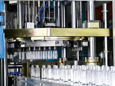
सामग्री कहाँ तक खिंच सकती है, यह तय करने के लिए तापमान का उपयोग करें।
परिधीय कंडीशनिंग
परिधीय कंडीशनिंग। अंडाकार और अनियमित आकार की बोतलों के लिए दिशात्मक तापीय नियंत्रण की आवश्यकता हो सकती है ताकि सामग्री लंबी धुरी में अत्यधिक न खिंच जाए। प्रीफॉर्म को लगातार अनुक्रमित करें और प्रमुख/लघु दीवार खंडों की तुलना करें। परिधीय कंडीशनिंग का परीक्षण करते समय आसन्न सेटिंग्स को स्थिर रखें और परिणाम को दीवार, आयाम या दृश्य डेटा से सत्यापित करें। परिधीय कंडीशनिंग के लिए सेटिंग या माप के बगल में बोतल की प्रतिक्रिया रिकॉर्ड करें; यह रिकॉर्ड परिधीय कंडीशनिंग की समीक्षा करते समय प्रारंभिक स्थिति बन जाता है। यदि स्थानांतरण के दौरान अभिविन्यास खो जाता है, तो अधिमान्य तापन बोतल के साथ संरेखित नहीं रह सकता है।
इस विशिष्ट कार्य के लिए कार्य शर्तें
- मोटाई मानचित्र
- कंधे, ऊपरी पार्श्व भाग, मध्य भाग, निचले पैनल, एड़ी और आधार पर माप बैंड परिभाषित करें, और प्रत्येक बैंड पर कई परिधीय बिंदु निर्धारित करें।
- प्रीफॉर्म द्रव्यमान वितरण
- प्रीफॉर्म की दीवार की मोटाई और टेपर यह निर्धारित करते हैं कि बोतल के प्रत्येक क्षेत्र के लिए कितनी सामग्री उपलब्ध है।
- अक्षीय तापीय प्रोफ़ाइल
- रेजिन प्रक्रिया की निर्धारित अवधि के भीतर, गर्म क्षेत्र आमतौर पर अधिक आसानी से फैलते हैं जबकि ठंडे क्षेत्र फैलने का प्रतिरोध करते हैं।
- परिधीय कंडीशनिंग
- अंडाकार और अनियमित आकार की बोतलों के लिए दिशात्मक तापीय नियंत्रण की आवश्यकता हो सकती है ताकि सामग्री लंबी धुरी में अत्यधिक न खिंच जाए।
अक्षीय खिंचाव को नियंत्रित करने के लिए रॉड की गति का उपयोग करें
रॉड स्टार्ट
रॉड स्टार्ट। स्ट्रेच रॉड के संपर्क में आने और प्रीफॉर्म को खींचना शुरू करने का क्षण इस बात को प्रभावित करता है कि रेडियल विस्तार से पहले कितनी सामग्री निचली बोतल की ओर बढ़ती है। तापमान और दबाव को स्थिर रखते हुए, समय को छोटे-छोटे चरणों में बदलें। रॉड स्टार्ट का परीक्षण करते समय आस-पास की सेटिंग्स को स्थिर रखें और परिणाम को दीवार, आयाम या दृश्य डेटा से सत्यापित करें। यदि लक्षण या प्रदर्शन लक्ष्य अनुमान के अनुसार नहीं बदलता है, तो रॉड स्टार्ट को बेसलाइन पर वापस लाएँ और स्टैकिंग सुधारों के बजाय रॉड स्टार्ट की जाँच करें। बहुत देर से स्ट्रेच करने से बोतल के ऊपरी हिस्से में अतिरिक्त सामग्री रह सकती है।
रॉड गति प्रोफ़ाइल
रॉड की गति का प्रोफाइल। नियंत्रित गति या बहु-चरणीय गति से यह निर्धारित किया जा सकता है कि प्रीफॉर्म के विभिन्न क्षेत्र कब विस्तार में प्रवेश करते हैं। उपलब्ध होने पर मशीन गति ट्रेस का उपयोग करें और आधार और पार्श्व दीवार की मोटाई में होने वाले परिवर्तनों को समझें। रॉड गति प्रोफ़ाइल का परीक्षण करते समय आसन्न सेटिंग्स को स्थिर रखें और परिणाम को दीवार, आयाम या दृश्य डेटा से सत्यापित करें। यदि किसी परिवर्तन से एक क्षेत्र में सुधार होता है लेकिन दूसरे में गिरावट आती है, तो पहले दृश्य सुधार को स्वीकार करने के बजाय रॉड गति प्रोफ़ाइल और रॉड गति प्रोफ़ाइल के बीच सामग्री या ऊर्जा की गति की तुलना करें। तेज़ रॉड का होना स्वतः बेहतर नहीं होता; इसे हवा और सामग्री के तापमान के साथ सिंक्रनाइज़ रहना चाहिए।
टूलिंग संबंधी निर्णयों के लिए, ASB-12 प्रतिस्थापन मोल्ड इंजीनियरिंग यह इस बात पर प्रकाश डालता है कि आयामी इंटरफेस, कूलिंग कनेक्शन, कैविटी ज्यामिति और ट्रांसफर अलाइनमेंट को मशीन सेटअप के हिस्से के रूप में क्यों माना जाना चाहिए।
| वस्तु | इंजीनियरिंग प्रश्न | व्यावहारिक सत्यापन |
|---|---|---|
| मोटाई मानचित्र | कंधे, ऊपरी पार्श्व भाग, मध्य भाग, निचले पैनल, एड़ी और आधार पर माप बैंड परिभाषित करें, और प्रत्येक बैंड पर कई परिधीय बिंदु निर्धारित करें। | प्रत्येक परीक्षण के लिए एक ही कट स्थान और उपकरण विधि का प्रयोग करें। |
| प्रीफॉर्म द्रव्यमान वितरण | प्रीफॉर्म की दीवार की मोटाई और टेपर यह निर्धारित करते हैं कि बोतल के प्रत्येक क्षेत्र के लिए कितनी सामग्री उपलब्ध है। | मशीन को ट्यून करने से पहले प्रीफॉर्म प्रोफाइल की तुलना बोतल की सतह के क्षेत्रफल और जटिल विशेषताओं से करें। |
| अक्षीय तापीय प्रोफ़ाइल | रेजिन प्रक्रिया की निर्धारित अवधि के भीतर, गर्म क्षेत्र आमतौर पर अधिक आसानी से फैलते हैं जबकि ठंडे क्षेत्र फैलने का प्रतिरोध करते हैं। | छोटे-छोटे क्षेत्रों में कंडीशनिंग को समायोजित करें और अगले मोटाई मानचित्र की तुलना करें। |
| परिधीय कंडीशनिंग | अंडाकार और अनियमित आकार की बोतलों के लिए दिशात्मक तापीय नियंत्रण की आवश्यकता हो सकती है ताकि सामग्री लंबी धुरी में अत्यधिक न खिंच जाए। | प्रीफॉर्म को लगातार अनुक्रमित करें और प्रमुख/लघु दीवार अनुभागों की तुलना करें। |
| रॉड स्टार्ट | जिस क्षण स्ट्रेच रॉड प्रीफॉर्म के संपर्क में आती है और उसे खींचना शुरू करती है, वह इस बात को प्रभावित करता है कि रेडियल विस्तार से पहले कितनी सामग्री निचली बोतल की ओर बढ़ती है। | तापमान और दबाव को स्थिर रखते हुए, समय को छोटे-छोटे चरणों में बदलें। |
| रॉड गति प्रोफ़ाइल | नियंत्रित गति या बहु-चरणीय गति यह निर्धारित कर सकती है कि प्रीफॉर्म के विभिन्न क्षेत्र कब विस्तार में प्रवेश करते हैं। | जहां उपलब्ध हो, मशीन की गति का विवरण प्राप्त करें और आधार और पार्श्व दीवार की मोटाई में होने वाले परिवर्तनों को उससे संबंधित करें। |
| रिलीज की स्थिति | प्रक्रिया के स्थिर अवस्था में पहुँचने के बाद, कैविटी की मोटाई और वजन मापें। कैविटी पहचान का उपयोग करके मशीन-व्यापी प्रक्रिया संबंधी समस्याओं को मोल्ड-विशिष्ट समस्याओं से अलग करें। | |
रेडियल विस्तार को नियंत्रित करने के लिए ब्लो टाइमिंग का उपयोग करें
प्री-ब्लो टाइमिंग
विस्फोट से पहले का समय। प्रारंभिक रेडियल विस्तार से अक्षीय वितरण पूरा होने से पहले ही सामग्री मोल्ड के विरुद्ध जम सकती है। प्री-ब्लो को धीरे-धीरे विलंबित या अग्रिम करें और शोल्डर-टू-बेस मोटाई स्थानांतरण की तुलना करें। प्री-ब्लो टाइमिंग का परीक्षण करते समय आसन्न सेटिंग्स को स्थिर रखें और परिणाम को दीवार, आयाम या दृश्य डेटा से सत्यापित करें। जहाँ परिणाम सामग्री ग्रेड या टूलिंग ज्यामिति पर निर्भर करता है, वहाँ स्वीकृत परियोजना सीमा की पुष्टि करें और फिर अगले क्रॉस-चेक के रूप में प्री-ब्लो टाइमिंग का उपयोग करें। अत्यधिक विलंब से प्रीफॉर्म अस्थिरता हो सकती है; अत्यधिक अग्रिम से निचली बोतल में सामग्री की कमी हो सकती है।
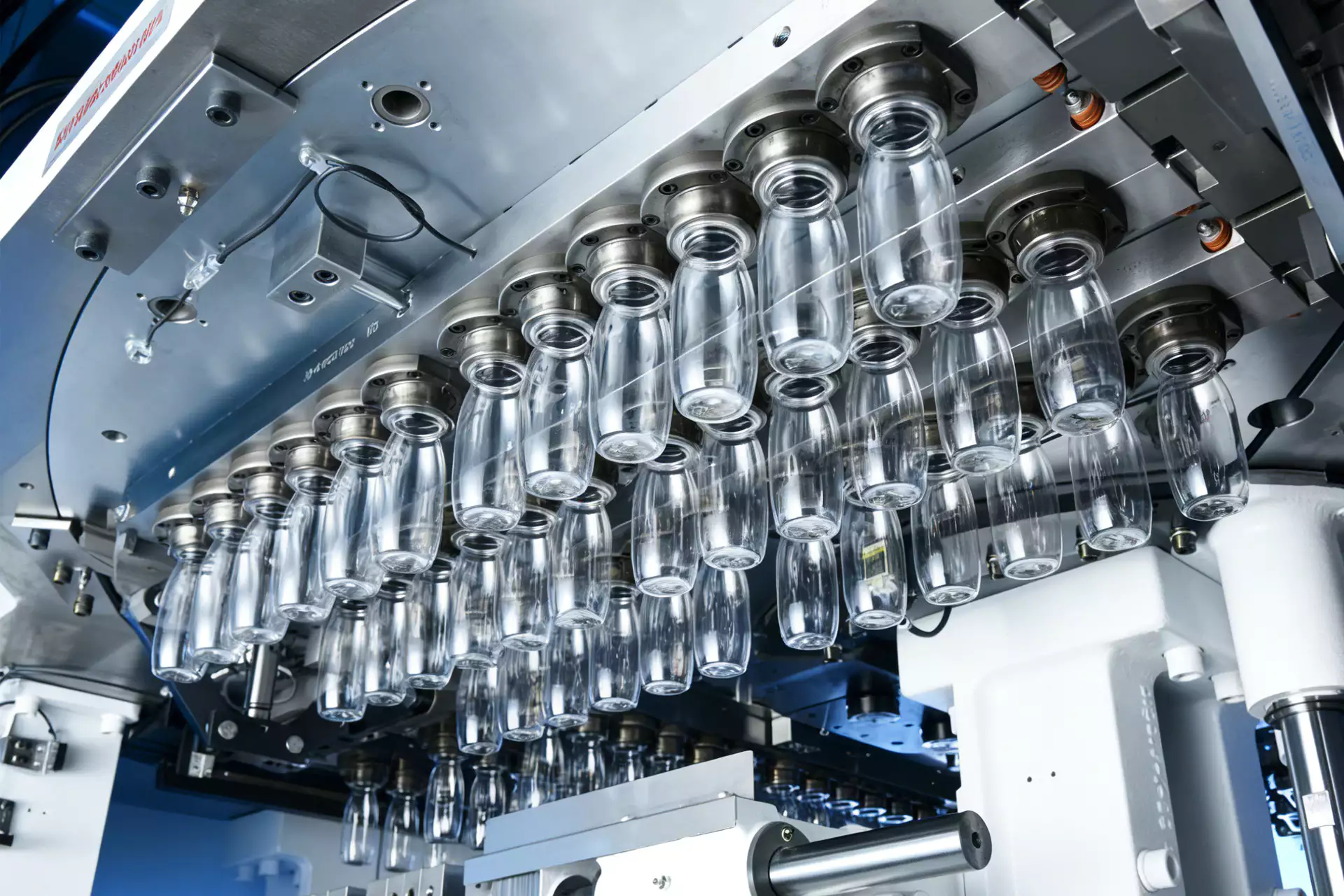
बेस, शोल्डर और पैनल के असंतुलन को अलग-अलग ठीक करें
अंतिम प्रहार और भड़ास निकालना
अंतिम प्रहार और भड़ास निकालना। अंतिम दबाव से मोल्ड के साथ पूर्ण संपर्क स्थापित होना चाहिए, लेकिन इसका उपयोग मोटाई नियंत्रण के मुख्य उपकरण के रूप में नहीं किया जाना चाहिए। दबाव बढ़ाने से पहले, अवरुद्ध वेंट या ठंडी सामग्री के कारण होने वाली कम स्पष्टता की जाँच करें। अंतिम ब्लो और वेंटिंग का परीक्षण करते समय आस-पास की सेटिंग्स को स्थिर रखें और परिणाम को दीवार, आयाम या दृश्य डेटा से सत्यापित करें। जब परियोजना मशीन या सामग्री की सीमा के करीब हो, तो एक मोल्डिंग परीक्षण आवश्यक करें जो अंतिम ब्लो और वेंटिंग को अलग करे और फिर उसी बोतल विनिर्देश के तहत अंतिम ब्लो और वेंटिंग की जाँच करें। उच्च दबाव सामग्री को कैविटी के विरुद्ध ठंडा होने के बाद नहीं हिला सकता।
मोल्ड शीतलन
मोल्ड को ठंडा करना। मोल्ड के तापमान में असमानता से स्थानीय जमने का समय और आकार बदल सकते हैं। जल सर्किट को संतुलित करें और अवरुद्ध चैनलों या उच्च वापसी-तापमान अंतरों की जांच करें। मोल्ड कूलिंग का परीक्षण करते समय आस-पास की सेटिंग्स को स्थिर रखें और परिणाम को दीवार, आकार या दृश्य डेटा से सत्यापित करें। सबसे सुरक्षित व्याख्या कम से कम कई स्थिर चक्रों की तुलना करके और फिर बाकी रेसिपी को बदले बिना मोल्ड कूलिंग को सत्यापित करके प्राप्त की जाती है। एक ही गर्म कैविटी समान रेसिपी सेटिंग्स के साथ भी बार-बार अलग-अलग दीवार प्रोफाइल उत्पन्न कर सकती है।
प्रत्येक कैविटी की जांच करें और प्रोसेस विंडो को लॉक करें।
गुहा सत्यापन
गुहा सत्यापन। प्रक्रिया के स्थिर अवस्था में पहुँचने के बाद कैविटी के अनुसार मोटाई और वजन मापें। कैविटी पहचान का उपयोग करके मशीन-व्यापी प्रक्रिया संबंधी समस्याओं को मोल्ड-विशिष्ट समस्याओं से अलग करें। कैविटी सत्यापन का परीक्षण करते समय आस-पास की सेटिंग्स को स्थिर रखें और परिणाम को दीवार, आयाम या दृश्य डेटा से सत्यापित करें। एक उपयोगी उत्पादन परीक्षण में कैविटी सत्यापन में परिवर्तन करते समय रेज़िन लॉट और कैविटी पहचान को स्थिर रखा जाता है, जिसके बाद कैविटी सत्यापन की अलग से जाँच की जाती है। बैच औसत एक ऐसी कैविटी को छिपा सकता है जो खतरनाक रूप से पतली बोतलें बनाती है।
मोल्ड कूलिंग: साक्ष्य जारी करें
सांचे के तापमान में असमानता से स्थानीय जमने का समय और आकार बदल सकते हैं। जल परिपथों को संतुलित करें और अवरुद्ध चैनलों या उच्च प्रतिगमन तापमान अंतरों की जांच करें। स्थिति तभी स्वीकार्य मानी जाएगी जब प्रक्रिया सामान्य परिचालन तापमान पर पहुंचने के बाद संबंधित बोतल का माप या कार्यात्मक परीक्षण स्थिर रहे।
गुहा सत्यापन: विफलता सीमा
बैच औसत एक ऐसी खामी को छुपा सकता है जिससे बोतलें खतरनाक रूप से पतली हो जाती हैं। परीक्षण के लिए उस विफलता मोड को सीमा मानिए और जब बोतल की प्रतिक्रिया गलत दिशा में जाने लगे तो पिछली स्थिर स्थिति में लौट आइए।
आवश्यकता को हार्डवेयर में रूपांतरित करते समय, HGY50-V3-EV मशीन विन्यास यह दर्शाता है कि इंजेक्शन, थर्मल कंडीशनिंग, स्ट्रेच-ब्लो मोशन और हैंडलिंग को एक कॉम्पैक्ट वन-स्टेप प्लेटफॉर्म पर कैसे व्यवस्थित किया जाता है।
आईएसबीएम में बोतल की दीवार की मोटाई को कैसे नियंत्रित किया जाए, इस विषय में विशेष रूप से उठने वाले प्रश्न।
पतले बेस के लिए मुझे सबसे पहले कौन सा वेरिएबल बदलना चाहिए?
सबसे पहले प्रीफॉर्म और मोटाई का नक्शा सत्यापित करें, फिर थर्मल प्रोफाइल और स्ट्रेच/प्री-ब्लो टाइमिंग की जांच करें। अंतिम दबाव को पहले बदलना शायद ही कभी सबसे उपयोगी कदम होता है।
क्या बोतल का वजन सही हो सकता है जबकि दीवार की मोटाई गलत हो?
जी हाँ। कंधे, पार्श्व दीवार और आधार के बीच समान द्रव्यमान का वितरण बहुत अलग-अलग हो सकता है।
परिधीय मोटाई क्यों मापी जाती है?
अंडाकार, हैंडल वाली और अनियमित आकार की बोतलों में परिधि के आसपास काफी अंतर हो सकता है, भले ही अक्षीय औसत स्वीकार्य प्रतीत हो।
क्या ठंडी प्रीफॉर्म सामग्री हमेशा मोटी हो जाती है?
यह कोई सार्वभौमिक नियम नहीं है। पदार्थ की गति पूरी तरह से तापीय, खिंचाव और वायु अनुक्रम पर निर्भर करती है, इसलिए माप लेकर परिवर्तनों की पुष्टि करें।
मुझे कैसे पता चलेगा कि किसी एक कैविटी में फफूंद की समस्या है?
कैविटी के कारण ट्रैक की मोटाई और दोष। किसी एक स्थान पर बार-बार होने वाली समस्या स्थानीय शीतलन, वेंटिंग, संरेखण या टूलिंग की स्थिति की ओर इशारा करती है।
व्यावहारिक निष्कर्ष
आईएसबीएम में बोतल की दीवार की मोटाई को नियंत्रित करने के तरीके का एक ठोस समाधान रीस्टार्ट और पूर्ण तापीय स्थिरीकरण अवधि के बाद भी प्रभावी रहना चाहिए। इसलिए, सेटअप रिकॉर्ड में मोटाई मानचित्र को रॉड गति प्रोफ़ाइल और कैविटी सत्यापन से प्राप्त बोतल के परिणाम से जोड़ा जाना चाहिए। तेज़ रॉड का होना अपने आप बेहतर नहीं है; इसे हवा और सामग्री के तापमान के साथ सिंक्रनाइज़ रहना चाहिए।