Servo vs Hydraulic ISBM Machines: Key Differences: Practical Technical Guide
This guide treats Servo vs Hydraulic ISBM Machines: Key Differences as a sequence of measurable decisions. It begins with the physical product requirement, then tests the process mechanisms that can change the bottle, and finishes with a release condition that can be documented.
Drive principleMaintenanceApplication fit
இந்தக் கட்டுரை நிரூபிக்க வேண்டியது என்னவென்றால்
Compare servo-driven and hydraulic motion systems in terms of precision, energy behavior, cleanliness, maintenance, dynamics and application fit. A defensible baseline begins with Servo-electric axes convert motor rotation directly through mechanical transmission, while hydraulic systems use pumps, valves and fluid pressure to create motion. The first verification method is Identify which axes on each proposed machine are actually electric or hydraulic because many machines use mixed architectures. From there, the article follows only checks that can materially change the answer promised by the title. Where an exact operating value depends on the resin grade, bottle drawing, mold, or delivered machine, the approved project specification controls the final setting.
✔️ Drive principle
Servo-electric axes convert motor rotation directly through mechanical transmission, while hydraulic systems use pumps, valves and fluid pressure to create motion. Identify which axes on each proposed machine are actually electric or hydraulic because many machines use mixed architectures.
✔️ Position control
Servo systems can provide direct programmable control of position, speed and acceleration on controlled axes; hydraulic motion depends on valve, pressure and feedback design. Compare repeatability on stretch rods, mold movement, injection or transfer where those motions affect bottle quality.
✔️ Energy at idle and part load
Electric servos generally draw power when doing work, while conventional hydraulic systems may circulate fluid or maintain pressure between motions. Review measured power across the full cycle, including pumps, heaters and cooling auxiliaries.
தி ASB-12 injection tooling replacement is a useful equipment example when the task involves mold exchange, dimensional matching, cooling performance, or repeatable transfer between ISBM stations.
What Changes When the Drive System Changes
Drive principle
Drive principle. Servo-electric axes convert motor rotation directly through mechanical transmission, while hydraulic systems use pumps, valves and fluid pressure to create motion. Identify which axes on each proposed machine are actually electric or hydraulic because many machines use mixed architectures. Compare both options against the same bottle geometry, resin, good-output target, and quality criteria when judging drive principle. A useful production trial keeps the resin lot and cavity identification fixed while drive principle is changed, followed by a separate check of drive principle. Calling a machine servo or hydraulic without an axis list can hide the systems that dominate performance.
Motion Precision and Repeatability
Position control
Position control. Servo systems can provide direct programmable control of position, speed and acceleration on controlled axes; hydraulic motion depends on valve, pressure and feedback design. Compare repeatability on stretch rods, mold movement, injection or transfer where those motions affect bottle quality. Compare both options against the same bottle geometry, resin, good-output target, and quality criteria when judging position control. The practical value of this check is that it turns position control from a vague setting into evidence that can be compared with position control. Precision claims matter only at the axis that controls the critical process event.
Energy at idle and part load
Energy at idle and part load. Electric servos generally draw power when doing work, while conventional hydraulic systems may circulate fluid or maintain pressure between motions. Review measured power across the full cycle, including pumps, heaters and cooling auxiliaries. Compare both options against the same bottle geometry, resin, good-output target, and quality criteria when judging energy at idle and part load. Use this result to narrow the process window, not to create a new universal setpoint; the next constraint to confirm is energy at idle and part load. Comparing motor nameplate ratings does not show real cycle energy.
Energy Use at Part Load
Heat generation
Heat generation. Hydraulic losses appear as heat in the oil and can increase cooling load; electric drives shift heat to motors and drives. Include machine cooling demand when calculating facility energy and HVAC impact. Compare both options against the same bottle geometry, resin, good-output target, and quality criteria when judging heat generation. The expected response should be visible in a bottle measurement, defect map, or machine trend before the team proceeds to heat generation. Ignoring rejected heat can underestimate chiller or room ventilation requirements.
இந்த குறிப்பிட்ட பணிக்கான பணி விதிமுறைகள்
- Drive principle
- Servo-electric axes convert motor rotation directly through mechanical transmission, while hydraulic systems use pumps, valves and fluid pressure to create motion.
- Position control
- Servo systems can provide direct programmable control of position, speed and acceleration on controlled axes; hydraulic motion depends on valve, pressure and feedback design.
- Energy at idle and part load
- Electric servos generally draw power when doing work, while conventional hydraulic systems may circulate fluid or maintain pressure between motions.
- Heat generation
- Hydraulic losses appear as heat in the oil and can increase cooling load; electric drives shift heat to motors and drives.
Cleanliness, Heat and Cooling
Cleanliness
Cleanliness. Hydraulic machines contain oil circuits and potential leak points; electric axes remove oil from those functions. For pharmaceutical or cosmetic production, review guarding, lubrication locations and contamination controls around the molding area. Compare both options against the same bottle geometry, resin, good-output target, and quality criteria when judging cleanliness. Once this check is stable, the next useful question is whether cleanliness changes the same bottle region or affects a different part of the process. An electric machine still contains grease and other service fluids, so cleanliness depends on total machine design.
Maintenance
Maintenance. Hydraulic systems require oil condition, filters, seals, pumps and valve maintenance; servo systems add drives, encoders, motors and mechanical transmissions. Compare preventive tasks, spare-part cost and technician skills for the actual machine. Compare both options against the same bottle geometry, resin, good-output target, and quality criteria when judging maintenance. This checkpoint should be evaluated before maintenance is altered, because otherwise two process mechanisms change at the same time. Maintenance does not disappear with servo technology; it changes form.
இந்தத் தலைப்பைப் பொறுத்தவரை, ஒரு-படி ISBM இயந்திர தொகுப்பு செயல்முறைத் தேவையை ஒரு ஒருங்கிணைந்த ரெசின்-டு-பாட்டில் தளத்துடன் இணைப்பதற்கு, பயனுள்ள உபகரணச் சூழலை வழங்குகிறது.
| பொருள் | பொறியியல் கேள்வி | நடைமுறைச் சோதனை |
|---|---|---|
| Drive principle | Servo-electric axes convert motor rotation directly through mechanical transmission, while hydraulic systems use pumps, valves and fluid pressure to create motion. | Identify which axes on each proposed machine are actually electric or hydraulic because many machines use mixed architectures. |
| Position control | Servo systems can provide direct programmable control of position, speed and acceleration on controlled axes; hydraulic motion depends on valve, pressure and feedback design. | Compare repeatability on stretch rods, mold movement, injection or transfer where those motions affect bottle quality. |
| Energy at idle and part load | Electric servos generally draw power when doing work, while conventional hydraulic systems may circulate fluid or maintain pressure between motions. | Review measured power across the full cycle, including pumps, heaters and cooling auxiliaries. |
| Heat generation | Hydraulic losses appear as heat in the oil and can increase cooling load; electric drives shift heat to motors and drives. | Include machine cooling demand when calculating facility energy and HVAC impact. |
| Cleanliness | Hydraulic machines contain oil circuits and potential leak points; electric axes remove oil from those functions. | For pharmaceutical or cosmetic production, review guarding, lubrication locations and contamination controls around the molding area. |
| Maintenance | Hydraulic systems require oil condition, filters, seals, pumps and valve maintenance; servo systems add drives, encoders, motors and mechanical transmissions. | Compare preventive tasks, spare-part cost and technician skills for the actual machine. |
| வெளியீட்டு நிபந்தனை | Clean-room-style production, short runs, frequent motion changes or energy constraints may favor more electric control; other projects prioritize simplicity, force density or existing maintenance skills. Weight the criteria that affect the intended bottles and factory rather than choosing by trend. | |
Maintenance and Failure Modes
Dynamic response
Dynamic response. Servo motion profiles can be programmed precisely, while high-quality hydraulics can deliver strong force and smooth motion. Evaluate acceleration, force requirements and synchronization on clamp, stretch and injection axes. Compare both options against the same bottle geometry, resin, good-output target, and quality criteria when judging dynamic response. For this topic, the engineering log should connect dynamic response with the observed bottle condition and then test whether dynamic response supports the same diagnosis. Choosing a technology from general reputation rather than required force and motion profile can waste investment.
Noise, Vibration and Operator Environment
Noise and vibration
Noise and vibration. Electric systems can reduce pump-related noise and vibration, especially when hydraulic pumps run continuously. Measure or observe the machine during a complete production cycle. Compare both options against the same bottle geometry, resin, good-output target, and quality criteria when judging noise and vibration. Do not judge this factor from the HMI value alone; pair it with the actual bottle result, then continue with noise and vibration only after the relationship is clear. Noise depends on compressors, pneumatics, mechanical impact and auxiliaries as well as the main drive.
Capital and life-cycle cost
Capital and life-cycle cost. Servo-rich designs may cost more initially but can reduce energy or maintenance in some duty profiles; hydraulic systems may offer familiar service and robust force generation. Model annual energy, cooling, maintenance, spare parts and downtime along with purchase price. Compare both options against the same bottle geometry, resin, good-output target, and quality criteria when judging capital and life-cycle cost. Keep capital and life-cycle cost at its validated baseline while this item is tested so the bottle response can be attributed to one cause. A technology label does not guarantee lower total cost in every plant.
How to Choose for the Actual ISBM Application
Application fit
Application fit. Clean-room-style production, short runs, frequent motion changes or energy constraints may favor more electric control; other projects prioritize simplicity, force density or existing maintenance skills. Weight the criteria that affect the intended bottles and factory rather than choosing by trend. Compare both options against the same bottle geometry, resin, good-output target, and quality criteria when judging application fit. Use the smallest controlled change that can prove the effect of application fit, then restore the baseline before a different adjustment such as application fit is tried. The best drive system is the one that keeps the validated molding process stable at acceptable life-cycle cost.
Capital and life-cycle cost: release evidence
Servo-rich designs may cost more initially but can reduce energy or maintenance in some duty profiles; hydraulic systems may offer familiar service and robust force generation. Model annual energy, cooling, maintenance, spare parts and downtime along with purchase price. The condition is accepted only when the relevant bottle measurement or functional test remains stable after the process reaches normal operating temperature.
Application fit: failure boundary
The best drive system is the one that keeps the validated molding process stable at acceptable life-cycle cost. Use that failure mode as the boundary for the trial and return to the previous stable condition when the bottle response moves in the wrong direction.
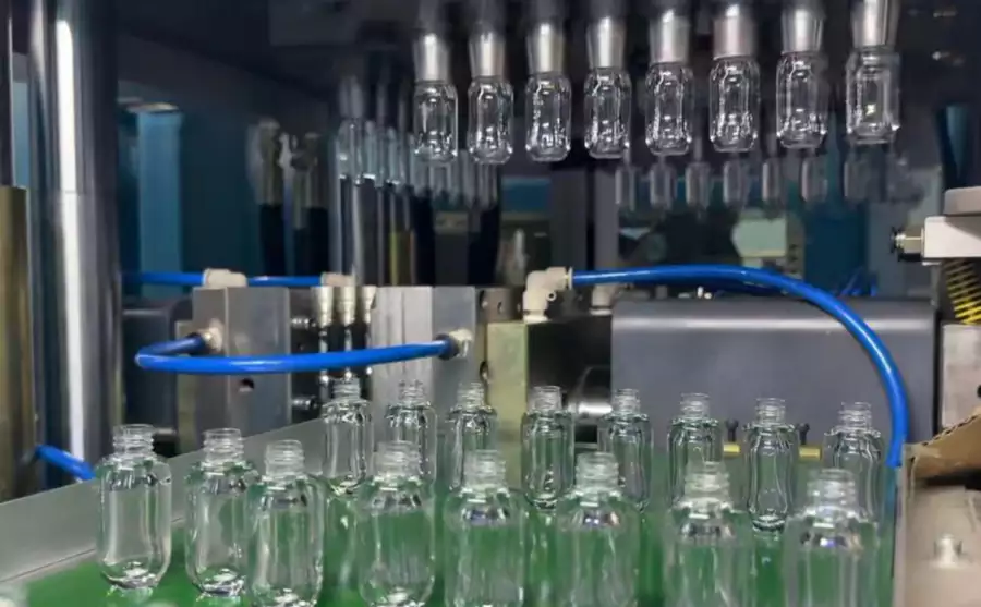
தேவையை வன்பொருளாக மாற்றும்போது, HGY50-V3-EV இயந்திர கட்டமைப்பு ஊசி செலுத்துதல், வெப்பச் சீரமைப்பு, இழுத்து ஊதும் இயக்கம் மற்றும் கையாளுதல் ஆகியவை ஒரு கச்சிதமான ஒற்றைப் படிநிலைத் தளத்தில் எவ்வாறு ஒழுங்கமைக்கப்பட்டுள்ளன என்பதை இது விளக்குகிறது.
Questions that arise specifically in Servo vs Hydraulic ISBM Machines: Key Differences
Is a servo ISBM machine fully electric?
Not always. Some machines use servo motors on selected axes while retaining hydraulics or pneumatics elsewhere. Ask for an axis-by-axis architecture.
Do servo machines always use less energy?
They can reduce losses on certain duty cycles, but total energy must include heaters, compressors, chillers and all machine auxiliaries.
Are hydraulic machines less precise?
Precision depends on the complete control system, sensors, valve design, mechanical stiffness and maintenance condition, not simply the presence of hydraulics.
Which is easier to maintain?
That depends on local skills and spare-part availability. Hydraulic and servo systems have different preventive tasks and failure modes.
Which is better for pharmaceutical bottles?
Cleanliness and repeatability can make servo-heavy designs attractive, but material handling, guarding, lubrication and validation requirements must be assessed for the whole system.
நடைமுறை முடிவு
For Servo vs Hydraulic ISBM Machines: Key Differences, begin by documenting drive principle, then test maintenance without moving unrelated settings, and release the process only after application fit is verified on every active cavity. The best drive system is the one that keeps the validated molding process stable at acceptable life-cycle cost.