
How to Choose ISBM Machine Cavity Count: Practical Technical Guide
For How to Choose ISBM Machine Cavity Count, the objective is not to find one universal setting. It is to prove which combination of demand per production hour, shot mass, and changeover time produces the required bottle under stable factory conditions.
Demand per production hourCooling demandPortfolio fit
What this article must prove
Choose a cavity count that satisfies output and unit-cost goals without overloading injection, cooling, blow-air, mold-space or changeover capability. A defensible baseline begins with Convert sales demand into required good bottles per scheduled molding hour. The first verification method is Include planned downtime, startup scrap and changeovers when setting the production target. From there, the article follows only checks that can materially change the answer promised by the title. Where an exact operating value depends on the resin grade, bottle drawing, mold, or delivered machine, the approved project specification controls the final setting.
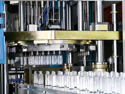
✔️ Demand per production hour
Convert sales demand into required good bottles per scheduled molding hour. Include planned downtime, startup scrap and changeovers when setting the production target.
✔️ Cycle estimate
Estimate a realistic cycle for the specific resin, wall thickness, neck, bottle geometry and machine architecture. Separate injection, cooling, transfer, conditioning, stretch-blow and ejection to identify the limiting segment.
✔️ Shot mass
Multiply preform mass by cavity count and compare with the injection unit operating window. Ask for the actual shot utilization and recovery-time calculation.
Cavity Count Is a System Decision
Demand per production hour
Demand per production hour. Convert sales demand into required good bottles per scheduled molding hour. Include planned downtime, startup scrap and changeovers when setting the production target. Turn demand per production hour into a written project requirement or operating range before comparing machine models. For this topic, the engineering log should connect demand per production hour with the observed bottle condition and then test whether demand per production hour supports the same diagnosis. Using calendar hours instead of actual molding hours leads to too few cavities.
For a compatibility check, the ASB-12 blow mold compatibility shows the kinds of mechanical and thermal interfaces that should be verified before a tooling or process change is released to production.
Start from Good Bottles per Hour
Cycle estimate
Cycle estimate. Estimate a realistic cycle for the specific resin, wall thickness, neck, bottle geometry and machine architecture. Separate injection, cooling, transfer, conditioning, stretch-blow and ejection to identify the limiting segment. Turn cycle estimate into a written project requirement or operating range before comparing machine models. Do not judge this factor from the HMI value alone; pair it with the actual bottle result, then continue with cycle estimate only after the relationship is clear. Assuming cycle time stays constant as cavitation increases can overstate output.
Shot mass
Shot mass. Multiply preform mass by cavity count and compare with the injection unit operating window. Ask for the actual shot utilization and recovery-time calculation. Turn shot mass into a written project requirement or operating range before comparing machine models. Keep shot mass at its validated baseline while this item is tested so the bottle response can be attributed to one cause. Excessive shot size can hit machine limits; very small shots on a large injection unit can create residence and control issues.
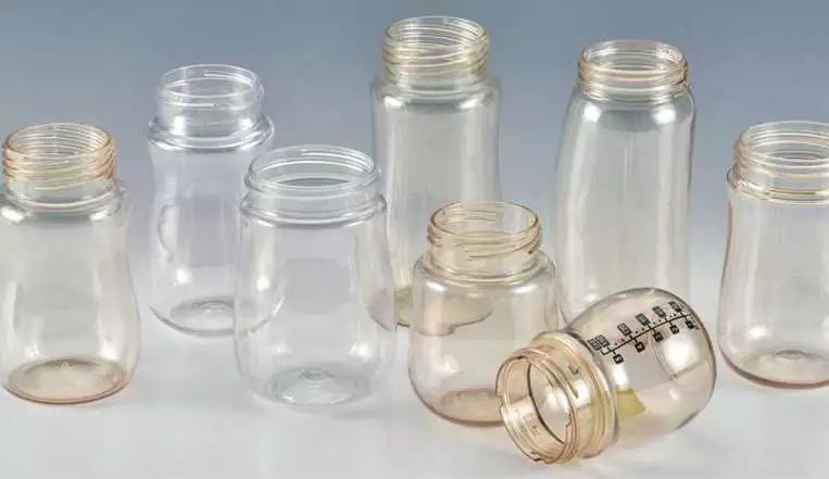
Check Shot Mass and Plasticizing Recovery
Mold width and pitch
Mold width and pitch. Use bottle diameter or width plus cavity walls, cooling passages and mechanical clearance to determine feasible pitch. Verify both injection and blow tooling because their spacing constraints may differ. Turn mold width and pitch into a written project requirement or operating range before comparing machine models. Use the smallest controlled change that can prove the effect of mold width and pitch, then restore the baseline before a different adjustment such as mold width and pitch is tried. The bottle may fit one side of the machine but not the other.
Working terms for this specific task
- Demand per production hour
- Convert sales demand into required good bottles per scheduled molding hour.
- Cycle estimate
- Estimate a realistic cycle for the specific resin, wall thickness, neck, bottle geometry and machine architecture.
- Shot mass
- Multiply preform mass by cavity count and compare with the injection unit operating window.
- Mold width and pitch
- Use bottle diameter or width plus cavity walls, cooling passages and mechanical clearance to determine feasible pitch.
Check Mold Pitch and Bottle Envelope
Neck spacing
Neck spacing. Check neck finish diameter, lip-cavity size and any orientation device. Lay out the neck components at the proposed cavity pitch and confirm room for cooling and fasteners. Turn neck spacing into a written project requirement or operating range before comparing machine models. This factor belongs in the setup sheet because it directly changes the conditions under which neck spacing is evaluated. Wide necks frequently reduce cavity count before bottle body diameter does.
Cooling demand
Cooling demand. More cavities increase heat removed from the resin each cycle and may require more mold water flow. Verify channel design, temperature rise and chiller capacity at the proposed cycle. Turn cooling demand into a written project requirement or operating range before comparing machine models. If the result differs by cavity, compare the local hardware related to cooling demand before moving on to cooling demand. An undercooled high-cavity mold can lengthen cycle or distort parts.
| Item | Engineering question | Practical verification |
|---|---|---|
| Demand per production hour | Convert sales demand into required good bottles per scheduled molding hour. | Include planned downtime, startup scrap and changeovers when setting the production target. |
| Cycle estimate | Estimate a realistic cycle for the specific resin, wall thickness, neck, bottle geometry and machine architecture. | Separate injection, cooling, transfer, conditioning, stretch-blow and ejection to identify the limiting segment. |
| Shot mass | Multiply preform mass by cavity count and compare with the injection unit operating window. | Ask for the actual shot utilization and recovery-time calculation. |
| Mold width and pitch | Use bottle diameter or width plus cavity walls, cooling passages and mechanical clearance to determine feasible pitch. | Verify both injection and blow tooling because their spacing constraints may differ. |
| Neck spacing | Check neck finish diameter, lip-cavity size and any orientation device. | Lay out the neck components at the proposed cavity pitch and confirm room for cooling and fasteners. |
| Cooling demand | More cavities increase heat removed from the resin each cycle and may require more mold water flow. | Verify channel design, temperature rise and chiller capacity at the proposed cycle. |
| Release condition | Select cavitation based on the combination of bottle families, not one forecast. Model high-volume and low-volume SKUs separately and consider shared tooling elements where practical. | |
Check Cooling and Blow-Air Demand
Blow-air demand
Blow-air demand. Cavities blow at the same synchronized event, creating a short high-flow demand. Check machine valve capacity, receiver sizing, header pressure stability and compressor recovery. Turn blow-air demand into a written project requirement or operating range before comparing machine models. This item is considered resolved only when the finding remains repeatable after thermal stabilization and the next check, blow-air demand, does not contradict it. Average compressor flow alone can hide a pressure sag during the blow pulse.
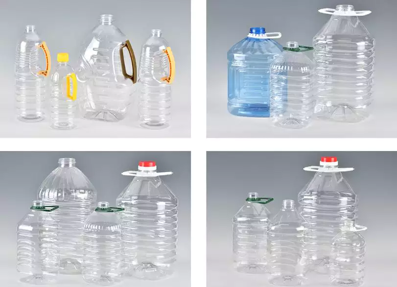
Compare Tooling Cost with Cycle Economics
Tooling cost
Tooling cost. Estimate complete mold cost and maintenance parts for each cavity scenario. Compare annualized tooling cost per good bottle rather than only upfront price. Turn tooling cost into a written project requirement or operating range before comparing machine models. For repeatability, define who measures tooling cost, where it is measured, and what bottle evidence is required before checking tooling cost. Very high cavitation can be uneconomic for frequent design changes or short product life.
The ISBM replacement mold design reinforces the practical need to control mounting geometry, thermal behavior, transfer position, and cavity alignment rather than treating the mold as an isolated component.
Changeover time
Changeover time. Larger molds weigh more, contain more components and can require more alignment work. Estimate lost production per changeover and lifting requirements for each cavity option. Turn changeover time into a written project requirement or operating range before comparing machine models. Record the bottle response beside the setting or measurement for changeover time; that record becomes the starting condition when changeover time is reviewed. A high-cavity machine in a high-mix plant may spend too much time out of production.
Select Cavitation for the Product Mix
Portfolio fit
Portfolio fit. Select cavitation based on the combination of bottle families, not one forecast. Model high-volume and low-volume SKUs separately and consider shared tooling elements where practical. Turn portfolio fit into a written project requirement or operating range before comparing machine models. If the symptom or performance target does not move as predicted, return portfolio fit to the baseline and investigate portfolio fit rather than stacking corrections. A cavity count optimized for one flagship bottle can be inefficient for the rest of the portfolio.
Changeover time: release evidence
Larger molds weigh more, contain more components and can require more alignment work. Estimate lost production per changeover and lifting requirements for each cavity option. The condition is accepted only when the relevant bottle measurement or functional test remains stable after the process reaches normal operating temperature.
Portfolio fit: failure boundary
A cavity count optimized for one flagship bottle can be inefficient for the rest of the portfolio. Use that failure mode as the boundary for the trial and return to the previous stable condition when the bottle response moves in the wrong direction.
Cavity-count calculation workflow
Begin with theoretical output = cavities × 3,600 / cycle time in seconds. Then calculate good output = theoretical output × process yield. If the plant schedules recurring changeovers or other losses, apply the planned availability separately rather than hiding those losses in an optimistic cycle estimate.
For each cavity scenario, also calculate shot mass = preform mass × cavities and resin throughput per hour. A cavity count should be rejected when it meets output on paper but pushes the injection unit, cooling circuit, mold width, or blow-air pulse beyond a comfortable operating window.
The ASB-compatible tooling configuration is also relevant when checking how mold interfaces and machine motion must remain compatible during replacement, troubleshooting, or capacity changes.
Questions that arise specifically in How to Choose ISBM Machine Cavity Count
Does doubling cavities double output?
Not necessarily. Injection recovery, cooling, mold size and air demand can lengthen the cycle, so output must be recalculated at the new cavitation.
Is the maximum cavity count always best?
No. The optimum is the lowest total cost that meets required good output and changeover needs.
Why do wide-mouth bottles reduce cavitation?
Large neck and lip components occupy more pitch and may need larger cooling and mechanical clearances.
How does cavitation affect compressor sizing?
More cavities increase the simultaneous blow-air pulse. The system must maintain required pressure and flow at the machine during that event.
Should different bottle sizes use different cavity counts?
Often yes. A machine may support several mold configurations, and each bottle should be evaluated for geometry, shot mass and economics.
Practical conclusion
The final decision on How to Choose ISBM Machine Cavity Count is made by the bottle, not by a single displayed parameter. Use demand per production hour to establish the input, cooling demand to test the mechanism, and portfolio fit to prove the output under stable conditions. A cavity count optimized for one flagship bottle can be inefficient for the rest of the portfolio.